Download
1 / 33
330 likes | 425 Views
Simple Instruction Pipelining. Krste Asanovic Laboratory for Computer Science Massachusetts Institute of Technology. Processor Performance Equation. Instructions per program depends on source code, compiler technology, and ISA

E N D
Simple Instruction Pipelining Krste Asanovic Laboratory for Computer Science Massachusetts Institute of Technology
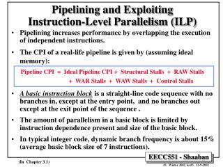
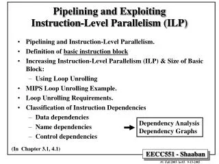
Processor Performance Equation • Instructions per program depends on source code, compiler technology, and ISA • Microcoded DLX from last lecture had cycles per instruction (CPI) of around 7 minimum • Time per cycle for microcoded DLX fixed by microcode cycle time — mostly ROM access + next μPC select logic Time = Instructions * Cycles * Time Program Program Instruction Cycle
Pipelined DLX To pipeline DLX: • First build unpipelined DLX with CPI=1 • Next, add pipeline registers to reduce cycle time while maintaining CPI=1
A Simple Memory Model WriteEnable Reads and writes are always completed in one cycle • a Read can be done any time (i.e. combinational) • a Write is performed at the rising clock edgeif it is enabled ⇒ the write address, data, and enable must be stable at the clock edge Clock Address MAGIC RAM ReadData WriteData
Datapath for ALU Instructions RegWrite clk Add we addr PC inst ALU clk Inst. Memory GPRs Imm Ext ALU Control RegDst ExtSel OpSel BSrc OpCode rf2 / rf3 Reg / Imm rf3 ← (rf1) func (rf2) func rf2 ← (rf1) op immediate immediate OpCode
Datapath for Memory Instructions Should program and data memory be separate? Harvard style: separate (Aiken and Mark 1 influence) - read-only program memory - read/write data memory at some level the two memories have to be the same Princeton style: the same (von Neumann’s influence) - A Load or Store instruction requires accessing the memory more than once during its execution
Load/Store Instructions: Harvard-Style Datapath RegWrite MemWrite WBSrc ALU / Mem clk Add we clk addr we PC inst ALU addr GPRs rdata Inst. Memory Data Memorywdata clk Imm Ext ALU Control OpCode RegDst ExtSel OpSel BSrc addressing mode (rf1) + displacement displacement OpCode rf1 is the base register rf2 is the destination of a Load or the source for a Store
Memory Hierarchy c.2002 Desktop & Small Server On-chip Caches Off-chip L3 Cache Hard Disk Interleaved Banks of DRAM SRAM/ eDRAM Proc < 25ns 15~50 clk 1~8MB ~150ns 100~300 clk 64M~1GB ~10ms seek time ~107 clk 20~100GB 0.5-2ns 2-3 clk 8~64KB <10ns 5~15 clk 0.25-2MB Our memory model is a good approximation of the hierarchical memory system when we hit in the on-chip cache
Conditional Branches PCSrc ( ~j / j ) RegWrite MemWrite WBSrc Add Add clk we clk addr PC we inst ALU addr clk Inst. Memory GPRs rdata Data Memorywdata Imm Ext ALU Control OpCode RegDst ExtSel OpSel BSrc zero?
Register-Indirect Jumps PCSrc ( ~j / j ) RegWrite MemWrite WBSrc Add Add clk we clk addr PC we inst ALU addr clk Inst. Memory GPRs rdata Data Memorywdata Imm Ext ALU Control Jump & Link? OpCode RegDst ExtSel OpSel BSrc zero?
Jump & Link RegWrite MemWrite WBSrc ALU / Mem / PC PCSrc Add Add clk we clk addr PC we inst ALU addr clk Inst. Memory GPRs rdata Data Memorywdata Imm Ext ALU Control zero? RegDst ExtSel OpSel BSrc OpCode rf3 / rf2 / R31
PC-Relative Jumps RegWrite MemWrite WBSrc ALU / Mem / PC PCSrc Add Add clk we clk addr PC we inst ALU addr clk Inst. Memory GPRs rdata Data Memorywdata Imm Ext ALU Control zero? RegDst ExtSel OpSel BSrc OpCode rf3 / rf2 / R31
Hardwired Control is pureCombinational Logic:Unpipelined DLX ExtSel BSrc OpSel MemWrite WBSrc RegDst RegWrite PCSrc op code combinational logic zero?
ALU Control & Immediate Extension Inst<5:0> (Func) Inst<31:26> (Opcode) ALUop OpSel ( Func, Op, +, 0? ) Decode Map ExtSel ( sExt16, uExt16, sExt26,High16)
Hardwired Control worksheet RegWrite MemWrite PCSrc PCR / RInd / ~j WBSrc ALU / Mem / PC Add Add Add we addr PC we inst ALU addr Inst. Memory rdata clk GPRs Data Memorywdata Imm Ext ALU Control BSrc Reg / Imm OpCode RegDst ExtSel OpSel rf3 / rf2 / R31 sExt16/uExt16/ sExt26/High16 Func/ Op/+/0? zero?
Hardwired Control Table • BSrc= Reg / Imm WBSrc= ALU / Mem / PC RegDst= rf2 / rf3 / R31 • PCSrc1 = j / ~j PCSrc2 = PCR / RInd
Hardwired Unpipelined Machine • Simple • One instruction per cycle • Why wasn’t this a popular machine style?
Unpipelined DLX Clock period must be sufficiently long for all of the following steps to be “completed”: • 1instruction fetch • decode and register fetch • ALU operation • data fetch if required • register write-back setup time ⇒ tC > tIFetch + tRFetch + tALU+ tDMem+ tRWB • At the rising edge of the following clock, the PC, the register file and the memory are updated
Pipelined DLX Datapath Add Clock period can be reduced by dividing the execution of an instruction into multiple cycles tC > max {tIF, tRF, tALU, tDM, tRW} = tDM (probably) However, CPI will increase unless instructions are pipelined we addr we IR rdata ALU addr GPRs rdata Inst. Memory Data Memorywdata Imm Ext write -back phase execute phase memory phase fetch phase decode & Reg-fetch phase
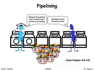
An Ideal Pipeline • All objects go through the same stages • No sharing of resources between any two stages • Propagation delay through all pipeline stages is equal • The scheduling of an object entering the pipeline is not affected by the objects in other stages These conditions generally hold for industrial assembly lines. An instruction pipeline, however, cannot satisfy the last condition. Why? stage stage stage stage
Pipelining History • Some very early machines had limited pipelined execution (e.g., Zuse Z4, WWII) • Usually overlap fetch of next instruction with current execution • IBM Stretch first major “supercomputer” incorporating extensive pipelining, result bypassing, and branch prediction • project started in 1954, delivered in 1961 • didn’t meet initial performance goal of 100x faster with 10x faster circuits • up to 11 macroinstructions in pipeline at same time • microcode engine highly pipelined also (up to 6 microinstructions in pipeline at same time) • Stretch was origin of 8-bit byte and lower case characters, carried on into IBM 360
How to divide the datapath into stages Suppose memory is significantly slower than other stages. In particular, suppose tIM = tDM = 10 units tALU = 5 units tRF= tRW= 1 unit Since the slowest stage determines the clock, it may be possible to combine some stages without any loss of performance
Minimizing Critical Path Add we addr we rdata ALU addr GPRs rdata Inst. Memory Data Memorywdata Imm Ext write -back phase memory phase fetch phase decode & Reg-fetch & execute phase tC > max {tIF, tRF, tALU, tDM, tRW} Write-back stage takes much less time than other stages. Suppose we combined it with the memory phase ⇒ increase the critical path by 10%
Maximum Speedup by Pipelining For the 4-stage pipeline, given tIM = tDM = 10 units, tALU = 5 units, tRF = tRW= 1 unit tC could be reduced from 27 units to 10 units ⇒ speedup = 2.7 However, if tIM = tDM = tALU = tRF = tRW = 5 units The same 4-stage pipeline can reduce tC from 25 units to 10 units ⇒ speedup = 2.5 But, since tIM = tDM = tALU = tRF = tRW , it is possible to achieve higher speedup with more stages in the pipeline. A 5-stage pipeline can reduce tC from 25 units to 5 units ⇒ speedup = 5
Technology Assumptions We will assume • A small amount of very fast memory (caches) backed up by a large, slower memory • Fast ALU (at least for integers) • Multiported Register files (slower!). It makes the following timing assumption valid tIM≈ tRF≈ tALU≈ tDM≈ tRW A 5-stage pipelined Harvard-style architecture will be the focus of our detailed design
5-Stage Pipelined Execution Add we we we addr addr rdata GPRs rdata Memory wdata Memory wdata Imm Ext write -back phase(WB) execute phase (EX) memory phase (MA) fetch phase (IF) decode & Reg-fetch phase (ID) time t0 t1 t2 t3 t4 t5 t6 t7 . . . . instruction1 IF1 ID1 EX1 MA1 WB1 instruction2 IF2 ID2 EX2 MA2 WB2 instruction3 IF3 ID3 EX3 MA3 WB3 instruction4 IF4 ID4 EX4 MA4 WB4 instruction5 IF5 ID5 EX5 MA5 WB5
5-Stage Pipelined Execution Resource Usage Diagram Add we we we addr addr rdata GPRs rdata Memory wdata Memory wdata Imm Ext write -back phase(WB) execute phase (EX) memory phase (MA) fetch phase (IF) decode & Reg-fetch phase (ID) time t0 t1 t2 t3 t4 t5 t6 t7 . . . . IF I1I2I3I4I5 ID I1I2I3I4I5 EX I1I2I3I4I5 MA I1I2I3I4I5 WB I1I2I3I4I5 Resources
Pipelined Execution: ALU Instructions not quite correct! Add we addr we rdata ALU addr Inst. Memory GPRs rdata Data Memorywdata Imm Ext MD1 MD2
Pipelined Execution: Need for Several IR’s Add we addr PC we ALU rdata addr GPRs Inst. Memory rdata Data Memorywdata Imm Ext MD1 MD2
IRs and Control points Add we addr PC we rdata ALU addr GPRs Inst. Memory rdata Data Memorywdata Imm Ext MD1 MD2 Are control points connected properly? -Load/Store instructions -ALU instructions
Pipelined DLX Datapathwithout jumps Add RegDst RegWrite we OpSel MemWrite WBSrc addr PC we ALU rdata addr GPRs rdata Inst. Memory Data Memorywdata Imm Ext MD1 MD2 ExtSel BSrc
How Instructions can Interact with each other in a Pipeline • An instruction in the pipeline may need a resource being used by another instruction in the pipeline structural hazard • An instruction may produce data that is needed by a later instruction data hazard • In the extreme case, an instruction may determine the next instruction to be executed control hazard (branches, interrupts,...)
Feedback to Resolve Hazards Controlling pipeline in this manner works provided the instruction at stage i+1 can complete without any interference from instructions in stages 1 to i (otherwise deadlocks may occur) Feedback to previous stages is used to stall or kill instructions FB1 FB2 FB3 FB4 stage stage stage stage