Download
1 / 32
320 likes | 501 Views
ELENA injection, extraction and transfer lines. W. Bartmann, B. Balhan, D. Barna, J. Borburgh, E. Carlier, T. Fowler, V. Namora, A. Prost, L. Sermeus, G. Vanbavinckhove, N. Voumard, H. Yamada ELENA Review, 15 th /16 th October 2013. Outline. P arameter table Injection Extraction

E N D
ELENA injection, extraction and transfer lines W. Bartmann, B. Balhan, D. Barna, J. Borburgh, E. Carlier, T. Fowler, V. Namora, A. Prost, L. Sermeus, G. Vanbavinckhove, N. Voumard, H. Yamada ELENA Review, 15th/16th October 2013
Outline • Parameter table • Injection • Extraction • Source for commissioning • Geometry of lines • Why electrostatic lines • Optics of lines • Electrostatic HW • List of potential issues ELENA review, Inj/extr and transfer lines
ELENA parameters ELENA review, Inj/extr and transfer lines
BT equipment limits ELENA review, Inj/extr and transfer lines
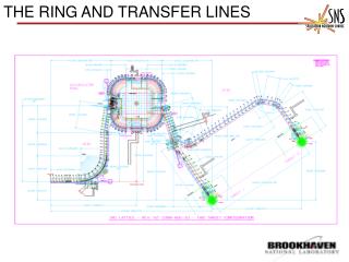
Sketch of TLs ELENA review, Inj/extr and transfer lines
Injection • Fast bunch-to-bucket transfer • Magnetic septum (295 mrad) • Magnetic kicker (84 mrad) ELENA review, Inj/extr and transfer lines
Injection kicker • Existing (1986), from AA ring • Magnet installed into new vacuum tank to be bakeableupt 300 deg in situ • HV power converter recuperated from AAC • PFL (SF6, 15 Ohm, 40kV) discharged by fast thyratron switches • Terminated by matched resistor • Pulse length can be adjusted with a dump thyratron • Polarity reversal by swapping HV in/out cables in magnet connection box ELENA review, Inj/extr and transfer lines
Injection septum • Existing, recovered from LEIR (SM12) • Full spare magnet available (since not used at extraction) • Magnetic performance (field homogeneity and leak field) to be measured within 2014 • Magnets need to be removed for bake-out requires dedicated support structure • Power supply covered by J. Baillie (TE-EPC) ELENA review, Inj/extr and transfer lines
Extraction • In Feasibility report (2010) the extraction was assumed to be magnetic with recuperated HW • Study of alternatives showed: • Also the electrostatic device allows to choose between extracting single bunches up to the full machine length increased flexibility and less prone to SC/IBS effects at flat bottom • Standardisation with fast switches in transfer lines • Choice for one electrostatic device for extraction instead of 2 magnetic ELENA review, Inj/extr and transfer lines
Electrode geometry and power supply • Electrode design from scratch • Power supply based on developments for Linac4 and Medaustron • Flat top and post pulse stability of 0.1% • corresponds to ~ few Volts ELENA review, Inj/extr and transfer lines
Why a source for commissioning? • The low energy part of ELENA (100keV) is reachable via an external source • ELENA will get every 100 s a shot from AD slow commissioning • ELENA ring installation shall be in 2015 while AD experiments still use the AD beam • Removal of existing magnetic and installation of electrostatic TLs will be one year later • As soon as the ring is installed, the source beam can be used to commission main accelerator systems • The source could also be used for re-commissioning of the machine and TLs after shutdowns before operational beams are available ELENA review, Inj/extr and transfer lines
Where to place the source? ELENA review, Inj/extr and transfer lines
Source operation modes • Want to use both beams, H- and protons • Protons via the extraction channel allows for keeping the ring polarity • Protons via injection channel for cooler tests (H- lifetime) ELENA review, Inj/extr and transfer lines
Why electrostatic transfer lines? • 100 keV is in the reachable range for electrostatic elements • Advantages • Cheap production, easy field shaping, no hysteresis, low power consumption, cheap power supplies, good magnetic shielding possibilities • Disadvantages • Vacuum compatibility of electrode material (outgassing), fault detection of bad connections, vacuum has to be opened for repair, interlocking against sparks ELENA review, Inj/extr and transfer lines
Geometry of lines • Optimisation of: • # bending angles in lines • Position of Elena ring wrt shielding • Straight extraction line to Gbar • Minimizing the ion switch angle ELENA review, Inj/extr and transfer lines
ALPHA line below ATRAP • ATRAP has two vertical lines branching off the line which leads further to ALPHA • Disturbance of 100 keV beam? • Measurements of stray field with ATRAP solenoids ON (without enhancing magnets – assume conservative factor 2 in addition) • Simulated in MADX the effect on the trajectory – up to 4 mm offset • Mitigation • Increased number of BPM/corrector pairs in this part of the line • Careful magnetic shielding of the area; need about a factor 10 reduction to compensate for factor 7 lower momentum compared to present situation (detailed studies to be conducted) • Higher number of quadrupoles than presently ELENA review, Inj/extr and transfer lines
Optics • Main challenge how to treat electrostatic elements • Quadrupoles: use magnetic quadrupole and adjust gradient according to voltages applied on electrodes • Bends: more complicated, calculate field shape from electrode geometry, track particles through field and fit transfer matrix, use this transfer matrix in MadX to calculate optics • Compare with different codes like COSY and WinAgile • Procedure rather extensive: changes in bending strength, trajectory correction ELENA review, Inj/extr and transfer lines
Beam parameters at experiments • Beam size of 1-2 mm • No particular request on dispersion, kept as free parameter to reduce number of quadrupoles • Dispersion added linearly for TL aperture calculations • Alphas not very important; keep reasonably small • Momentum spread not very critical for most experiments but Gbar • Dp/p (95%) < 2.5e-3 • Discussion next week to optimise beam parameters for Gbar ELENA review, Inj/extr and transfer lines
Optics for ATRAP 1 • 90 deg FODO as standard where possible • Quadrupolecentre to centre distance in FODO is 1.5 m • +/-1.7 kV for FODO • +/- 13 kV in matching sections • Matching of beam size at experiment, leave dispersion as free parameter in matching area to reduce number of quadrupoles • Beam sizes in lines limited to 2/3 of the physical aperture • Trajectory correction studies H/V correctors at 90 deg ELENA review, Inj/extr and transfer lines
Number of elements (incl spares) ELENA review, Inj/extr and transfer lines
Electrostatic Quadrupoles • Cylindrical electrodes: • avoid higher E-fields for hyperbolic ones due to smaller gap • Extruded aluminium profiles • 100 mm long • Quadrupoles mounted on flanges, every 1.4 m in FODO structure • In matching sections • several quads spaced by 5 cm mounted on longitudinal rail supported on both sides • Aperture disks in between define fringe fields • No alignment possibility of electrodes inside vacuum foreseen • Field distortion due to electrical connections negligible • Vacuum chamber of 200 mm diameter (reduced in vicinity to extraction) • ~100 elements ELENA review, Inj/extr and transfer lines
Steerers • Integrated on same rail as quadrupoles • Trajectory correction studies showed the necessity of dual plane correctors with 90 deg phase advance • Checked the emittanceincrease due to field distortion of second electrode pair • Assuming an 8 mrad kick (10 mm displacement at downstream quad): • 1-2% increase of rms emittance for 60 mm opening • no significant increase for 90 mm opening ELENA review, Inj/extr and transfer lines
Deflectors I • Electrostatic deflectors introduce strong focussing • Spherical deflectors (focussing in both planes) • Emittance growth due to field imperfections larger bending radii and electrode height preferable • Choice for 500 mm radius for all transverse bends, reduces also required voltage • Vertical bends ELENA review, Inj/extr and transfer lines
Deflectors II • Choice for 500 mm bending radius and electrode height of 180 mm • Reduces also required voltage • Operating voltage optimum • Minimum variation of energy • Balanced focussing properties in both planes ELENA review, Inj/extr and transfer lines
Fast switch + deflector • We have a total of 12 bends of which 7 are combined with a fast switch • Fast switch is standardized in specification and mechanical layout with the fast deflector for extraction • 3-4 types of bends ELENA review, Inj/extr and transfer lines
Ion switch • Need to deflect H- and p+ by 42 deg into extraction and injection line • Same time the injected and extracted antiproton beam has to pass the device • Use only two high-voltages • Fabrication in the CERN workshop • Single item • 316LN • Foreseen to test this device together with the source at Juelich ELENA review, Inj/extr and transfer lines
Items which deserve attention • Simulation of electrostatic elements • External collaboration with Triumf and Cockroft • Magnetic shielding around ATRAP • Source • Beam parameters from source • Current vs vacuum load vs beam parameters • Vacuum: differential pumping needed, need a more detailed step into the integration of the source elements • NEG coating in TLs? • Depends on requirements from the experiments • Compatibility with magnetic shielding • Experiment handover points ELENA review, Inj/extr and transfer lines
Spare slides ELENA review, Inj/extr and transfer lines
Septum parameters (max, 1152A) ELENA review, Inj/extr and transfer lines
Injection kicker parameters ELENA review, Inj/extr and transfer lines
Cost estimate • Total cost of 6.6 MCHF for ~110 m transfer lines • Including spares • Fast switches include also the extraction kickers • Not including: • Magnetic elements of LNI • Vacuum pumps, gauges, valves, bake out equipment • No cost splitting for • BI contribution from Tokyo which accounts for ½ of the instrumentation • GBAR TL • 2nd ASACUSA line, BASE, source line ELENA review, Inj/extr and transfer lines
Installation dates by line ELENA review, Inj/extr and transfer lines