Download
1 / 26
260 likes | 339 Views
CO2 Transfer lines. From cooling plant in USC to the Pixel Detector at the center of the solenoid there are 4 different stretches of transfer lines for the CO2 coolant: From the cooling plant in USC55 to the manifolds in UXC55 X3 balconies Near side (2 inlet and 2 outlet pipes ) [n.1]

E N D
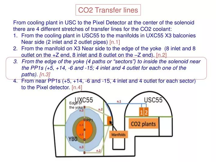
CO2 Transfer lines From cooling plant in USC to the Pixel Detector at the center of the solenoid there are 4 different stretches of transfer lines for the CO2 coolant: From the cooling plant in USC55 to the manifolds in UXC55 X3 balconies Near side (2 inlet and 2 outlet pipes) [n.1] From the manifold on X3 Near side to the edge of the yoke (8 inlet and 8 outlet on the +Z end, 8 inlet and 8 outlet on the –Z end). [n.2] From the edge of the yoke (4 paths or “sectors”) to inside the solenoid near the PP1s (+5, +14, -6 and -15; 4 inlet and 4 outlet for each one of the paths). [n.3] From near PP1s (+5, +14, -6 and -15, 4 inlet and 4 outlet for each sector) to the Pixel detector. [n.4] Edge of the yoke PP1
Sector (+5) Vacuum ports (optional)
Sector (+5) M12 M8 M8
PP1 110 mm 300 mm 50 mm 8 pipes in line Cut slots
PP1 +14C 110 mm
200 mm Top insulation layer 50 mm outlet: 10mm OD Bottom insulation layer Inlet: 6mm OD ~22 mm
CO2 cooling pipes schematics for BPIX +Z end All BPIX pipes through PP1 +14C INLET capillaries OUTLET Edge of Pixel bore Connection line Pixel Seal CONNECTION (VCR) Edge of Tk BH (e) To be decided (d) (a) (c) (b) L1D1PN PML1 L1D2PF L2D2PN PML2 L2D2PF L3D2PN L3D3PF L3D4PN PML3 L3D1PF manifold L4D1PN L4D4PF L4D3PN PML4 L4D2PF PP1 +14C BPIX +Z PP0 region Pixel bore From edge of Yoke to first connection after the flexible is provided by DeMaCo Edge of YOKE
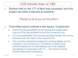
A few points to discuss: Need feedback for the supports (type and spacing) on the vacuum tank. If OK we will start welding the M8 studs Wednesday. Green light for the supports given. Support studs welded on the vac-tank We will design the supports for inside the vacuum tank when we receive feedback on the design. In progress… Connection box: aluminum plate, then Armaflex, then cover: studs can be welded to the tank or the yoke, you have to be able to connect to M8 15 or 20 mm, position not the same in all spots…. OK Size of connection boxes: in DWG 700x290x134, can it be reduced to 650x250x120? Very critical for sector +14 middle connection box Smaller size agreed Connection boxes: is vacuum connection fitting in the envelope? YES
A few points to discuss: Vacuum ports on face of the vacuum tank are optional. It was decided NOT to implement this option Planning (Jan?) All in one shot. When is you latest moment for confirming the date of installation? We requested DeMaCo to assume in their offer that the installation will take place in one shot (both ends in series) starting week 2, 2014. Option for a split installation should be mentioned with the additional cost. Request to modify the schedule has been made to CMS. Updated offer by end of August, order on first week of September. Still waiting….
CO2 pipes installation Martin.Gastal@cern.ch