Download
1 / 60
600 likes | 753 Views
IEC Experiments at UIUC. George H. Miley and colleagues in IEC group Dept. of Nuclear, Plasma, and Radiological Engineering University of Illinois, Urbana, IL. 61801 Other presentations from UIUC Hugo Leon et al on UIUC experimental facilities

E N D
IEC Experiments at UIUC George H. Miley and colleagues in IEC group Dept. of Nuclear, Plasma, and Radiological Engineering University of Illinois, Urbana, IL. 61801 Other presentations from UIUC Hugo Leon et al on UIUC experimental facilities Guilherme Amadio, Ben Ulmen, et al. on plasma jet
“Side” comment/request • Hope for help with proposed IEC monograph – Springer Verlag Scientific Press. • Scheduled next summer • Send any suggested inputs to me. Please cc Autumn West [ajwest85@gmail.com] • Coverage • Theory • Experiments • applications
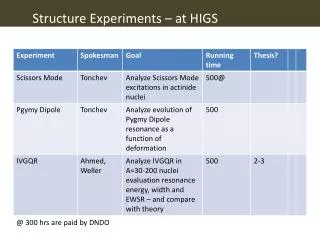
Outline - recent work has stressed alternate applications and IEC plasma use vs. IEC power reactors • Continued work on neutron sources • IEC bombardment studies • X-ray emission during high current ion bombardment • Measurement of low energy cross sections and facing wall effects • Controlled filament discharge concept • Theoretical studies of scale-up to power reactor • Potential well theory – cont’d of H-j Kim and H. Momota’s studies • Space thruster • Proton thrust technology • Jet thruster • dipole assisted IEC • Space ship I and II design studies • Plasma jet • waste processor • IEC driven fission research reactor (fusion-fission hybrid)
Space Probe Application of IEC Thrusters George H. Miley1*, Guilherme Amadio1, Ben Ulman1, Hiromu Momota1, Linchun Wu1, Michael Reilly1, Rodney Burton2, Vince Teofilo3, Dick Dell4, Richard Dell4 and William A. Hargus5 1Dept. of Nuclear, Plasma andRadiological Engineering, U of Illinois, Urbana, IL 61801;2Dept. of Aerospace Engineering, U of Illinois, Urbana, IL 61801; 3Lockheed Martin Space Systems Co., Advanced Technology Center, Palo Alto, CA 94304; 4Advanced Aerospace Resource Center (AARC), P.O. Box 97636, Raleigh, N.C. 27624, 5Air Force Research Laboratory, Edwards AFB, CA 93524 f
DESCRIPTION OF CONCEPT AND APPLICATIONS • Novel plasma jet thruster, based on Inertial Electrostatic Confinement (IEC) technology, -for ultra maneuverable - space thruster for satellite and small probe thrust operations. • Electrical efficiency matches conventional plasma thrusters; • design simplicity • reduced erosion giving long life timer • reduced propellant leakage losses • high power-to-weight ratio • Multiple jets ok for added control • Low gas leakage + good heat removal make it possible to scale the design to low powers or high powers.
Dipole-Assisted IEC for Space Propulsion R. Thomas and Y. Takeyama University of Illinois at Urbana-Champaign, Urbana, IL, 61801 G.H. Mileyand P.J. Shrestha NPL Associates Inc. 912 W. Armory, Champaign, IL, 61821
DaIEC (a) Dipole magnetic field and (b) layout of devices • Coil Specs: • 12 gage of Sq. magnet wire (Copper) • 17 x 26 turns of coil • Current Varies in the range of 0-20 A • Max. field strength of 0.1 T Coil Inner radius = 2 cm Outer radius = 8 cm Height = 4 cm Grid 20 cm radius 2 cm x 1cm spacing
Stabilizing coil Dipole reactor propulsion scheme – the field lines both focus injected ions and collimate the exhaust.
A small DaIEC was constructed to provide a proof-of-principle experiment.
A triple probe was inserted to measure density and temperature.
Photographs verify the dipole focusing effect when the magnetic field is on (right) vs. off (left).
Summary of PoP Study, and a graph of Electron Density vs. B-field. • Magnetic field increases the electron density by a factor of 16. • Electron temperature decreases in the presence of a magnetic field • the discharge voltage decreases in the presence of a magnetic field • The magnetic coil can be used to impose a potential in the central plasma to control space charge build up • Overall, the use of the dipole provides improved ion beam focusing, ion confinement, and also appears to favorably affect the discharge voltage characteristics.
High-Current, Low-Energy Deuterium Glow Discharge for Studies of Non-Linear Effects in Plasma Facing Materials Uses IEC in low discharge mode for bombardment of targets. Experiments done in collaboration with A. Lipson at Institute of Physics & Chem, Moscow AS, Russia
Background • Evaluation of DD and DT-reactions at the first wall surface of fusion reactors like ITER neglect effects of non-linear processes during high current, low energy bombardment. • Especially crucial as the concentrations of D and T atoms embedded in the wall surface increases = a “target” for bombarding ions. • Conventional (free space) DD-reaction cross-sections predict the DD-reactions are negligible at the low energies (≤2 keV) involved. But, the free space approximation is not accurate for the conditions involved. • The DD-reaction yield can be orders of magnitude higher than predicted by extrapolation of the standard (free space) DD-reaction cross-section to lower deuteron energies. These enhancement (non-linear) effects came from a drastic increase in the deuteron screening potential in the crystalline structure of the metal targets at Ed ~ 1.0 keV, especially at a high deuteron current density where the ion density in the target can become quite large.
Astrophysical physics connection • Nuclear reactions in astrophysical objects also encounter screening conditions similar to this. Consequently studies of metal targets bombarded by low energy accelerators has been strongly studied by groups such as the European Astrophysical Lab (LUNA) [ while time integrated yields become large (hence limiting wall lifetimes), the instantaneous yields are low. • Thus the key to accurate measurements involves using high current bombardment plus special detectors such as CR-39 tracking foils to measure charged particle emission during bombardment.
Modified IEC Pulsed Glow Discharge offers High Currrents needed
A photograph of a pulsed high current GD discharge from the top port AiAA 2008
Typical data from Cr-39 3.0 MeV proton yield detected by 11 m Al covered CR-39 detectors in deuterium GD at the same current and different accelerating voltages: U1 = 805 V and U2 = 2175 V
Yield of 3.0 MeV protons at 0.8 < Ed < 2.45 keV, normalized to that at Ed = 2.45 keV. The bare cross-section corresponded to Bosch and Halle approximation to Ed 2.45 keV is marked by a solid line. The dashed line is a DD-reaction yield =in accordance with a screening potential value Ue= 610 eV.
DD-reaction enhancement factor for the Ti target during deuteron bombardment with accelerator (curve 1) and glow discharge (curve 2). The solid parts = ranges the yield was measured experimentally.
Summary of prel. experiments • In accelerator measurements with the Ti-target at 2.5 < Ed < 10.0 keV, the deduced screening potential is Ue = 65 10 eV However, for the PGD experiment, the screening potential is as large as Us=620 140 eV • = enhancement in terms of DD-proton yield even at Ed=1.0 keV is about nine orders of magnitude larger than that predicted with bare (B&H) cross-section. • Illustrates how importance of higher deuteron/electron densities in the target (due to the higher currents in the GD) • In addition to fusion plasma wall effects, these densities are also representative of reactions in Astrophysical plasmas
Controlled Filament Non-Local Discharge (CFND) for Pulsed Electric Discharge Lasers and Plasma Chemistry Reactors George H. Miley, Hugo Leon, Atuna Khan Department of Nuclear, Plasma, and Radiological Engineering, University of Illinois, Urbana, 61801 AiAA 2008
Abstract • A new type of low E/N discharge, the Controlled Filament Non-local Discharge (CFND), is described. • Unique cathode design with a “spiked” surface and built-in ballast resistors, stabilize electron filaments generated during pulsed operation. • Potential applications to the Electric Oil Laser and various plasma processes such as ozone production are discussed. AiAA 2008
Atomic Iodine Transfer Laser • Based on energy transfer from metastable O2 (1∆) (SDO) to excite the I*(2P1/2) 1.31 μm I (2F3/2) transition. • The SDO generated chemically ⇨transferred by gas flow to a laser cell ⇨mixed with I2. • Results dissociation of I2⇨subsequent formation of I*(2P1/2) by the fast near resonant energy-transfer reaction: O2(1∆) + I(2P3/2) ⇆ O2(3Σ) + I*(2P1/2) AiAA 2008
CFND is intended to overcome limitations of COIL • Chemical approach of the operation of a chemical SDO generator suffers from several factors: ↠Limitations to the generation of high SDO density↠Need for cooling ↠Involvement of corrosive materials • Operation times typically restricted by formation of chemical by-products, eventually limit the production of SDO. AiAA 2008
Control of Electron Energy Distribution (EED) Electron excitation and ionization cross sections for oxygen. AiAA 2008
Micro-projection (spiked) Cathode Construction for the CFND AiAA 2008
Equivalent Electrical Circuit for Cathode-Anode Arrangement AiAA 2008
Magnetic Fields Associated with the CFND The magnetic fields associated with the CFND consist of an overall poloidal field around the entire discharge and individual fields around each filament. This configuration is, in effect, analogous to a wire cage Z-pinch plasma without physical wires. AiAA 2008
Analogy with Dielectric Barrier Discharge (DBD or “Silent Discharge”) • Another way of viewing the CFND: analogy with dielectric barrier discharge (DBD or “silent discharge”). • The dielectric coating on one of the electrodes limits the charge in the micro-discharge channel. • The micro channel formation and discharge are random in time and to some extent in space. • Estimated after initial breakdown at 600 V, an E/N of 10-16 Vcm2 is obtained at roughly atmospheric pressure in oxygen with an applied voltage of 100 V in planar electrode geometry at a spacing of ~10 cm. AiAA 2008
CFND Stability Issues • Stability of the CFND configuration is a crucial issue relative to extended discharge times and filament lengths. • Goal - to maintain stable filaments long enough to provide significant non-equilibrium reaction conditions. (e.g. efficient production of SDO in an oxygen discharge) • CFND holds great promise for enhanced stability ⇨can be viewed as a plasma analogy of the famous Sandia wire cage Z-pinch, currently producing world record x-ray yields. AiAA 2008
1-D Theoretical Model • A 1-D theoretical model has been constructed with features very similar to that used in earlier work by Eliasson et al. to very successfully model trends in the DBD filament discharge. • This model is used to compare trends in E/N as a function of pressure, voltage, and filament dimensions. AiAA 2008
A schematic diagram of 1-D spatial distribution of electrons, oxygen and ozone at O3 AiAA 2008
SDO Formation in Micro-Discharge Reactions • Reactions that involve electrons must be considered: positive ions O+, negative ions 0-, O; ground states O(3P), 02(X3E,), O3(lA1) and excited states O('D), 02(a'A,), OZ(b' X:), Oz(A 3E:), 02(B 3Z:), 02(v) and O: where 0:stands for a vibrationally-excited O3 molecule. • Reaction analysis limited to ~12 key equations, although a more complete analysis with a large number of reactions could eventually be done. AiAA 2008
A Schematic View of the CFND setup AiAA 2008
Initial experiment designed to allow room for internal diagnostics; adjust anode/cathode separation AiAA 2008
Special pulsed power supply is used to provide a fast rise time “square” pulse waveform with variable time duration The 2.2 kVA power supply built by NPL employees is shown above. The circuit board controlling the frequency operates between 100 Hz to 1800 Hz and the pulse width modulation operates with duty cycles from 5% to 95%. AiAA 2008
Illustrative V-I Curves AiAA 2008
Conclusion • Non-local effects in CFND plasma discharges offer unique opportunity to control the EED to enhance efficiency for excited state production, light emission, and select chemical reactions. • A very important application of this type is SDO production. • CFND approach- extremely well suited to such operation ⇨ optimum E/N can be achieved in a relatively high pressure, large volume plasma. • CNDF builds on prior use of filament type discharges for non-equilibrium processes. • Initial experimental set up and computational model have been described which are being employed for continuing studies of CFND. AiAA 2008
DRIVEN SUBCRITICAL FISSION SYSTEMS USING A CYLINDRICAL INERTIAL ELECTROSTATIC CONFINEMENT (IEC) NEUTRON SOURCE Miley G. H., Thomas R., Takeyama Y., Wu L., Percel I., Momota H., Hora H2., Li X. Z3. and P. J. Shrestha4 1University of Illinois, Urbana, IL, USA 2University of New South Wales, Sydney, NSW, Australia 3Tsinghua University, Beijing, China 4NPL Associates, Inc., Champaign, IL, USA DOE FF Hybrid WS Gaithersburg MD 9/09
Introduction – IEC driven subcritial systems • The IEC is already a commercial fusion neutron source at low levels!! • Replaced Cf-252 in neutron activation analysis at: • Ore mines in Germany • Coal mines in USA • In these cases ease of licensing, long lived “target” (plasma), on-off capability, simplicity of construction (low cost), compactness, low maintenance requirement, flexibility in neutron spectrum (2.54 or 14 MeV), ease of control gave the IEC the “edge”. The features can carry over to a driver for a hybrid. • Possibility of small size/power opens door to several near term applications = university training and research facilities. DOE FF Hybrid WS Gaithersburg MD 9/09
Flexible geometry offers new types of drive configurations --- Fig. 1 Spherical IEC Device Fig. 2 Cylindrical IEC Device ICONE-10 April 2002, Arlington, Virginia
Cylindrical IECs • Cylindrical IECs offer many advantages for the present sub-critical reactor system . • The prototype cylindrical IEC version , C-device, is a particularly attractive. • Deuterium (or D-T) beams in a hollow cathode configuration give fusion along the extended colliding beam volume in the center of the device = a line-type neutron source. DOE FF Hybrid WS Gaithersburg MD 9/09
IEC Modular Cylindrical Design Advantage • Accelerator approaches to date have used an accelerator spallation-target system. • The large size and cost of the accelerator remain an issue. Also, the in-core target system poses significant design and engineering complications. • The IEC fits in fuel element openings of the sub-critical core assembly. This provides a distributed source of neutrons • Replaces both the accelerator system and spallation-target by by multiple modular sources assembly. • Provides flexibility in core design and in flux profile control. • Small IEC units can be produced at a lower cost than the accelerator DOE FF Hybrid WS Gaithersburg MD 9/09
Top Cross-Section View Shows C-Device Modules in Channel Locations