Download
1 / 27
270 likes | 272 Views
Enterprise and Wide Area Networks. ITEC 370 George Vaughan Franklin University. Sources for Slides. Material in these slides comes primarily from course text, Guide to Networking Essentials,Tomsho, Tittel, Johnson (2007). Other sources are cited in line and listed in reference section.

E N D
Enterprise and Wide Area Networks ITEC 370 George Vaughan Franklin University
Sources for Slides • Material in these slides comes primarily from course text, Guide to Networking Essentials,Tomsho, Tittel, Johnson (2007). • Other sources are cited in line and listed in reference section.
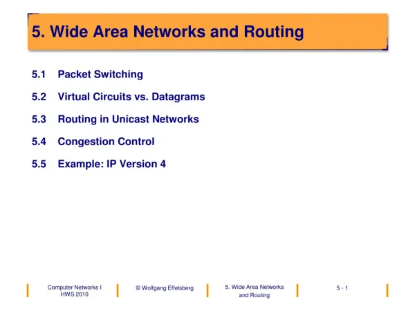
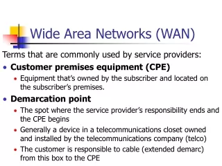
Creating Larger NetworksTomsho, Tittel, Johnson (2007) • Ways to stretch or expand network capabilities • Physically expanding to support additional computers • Segmenting the network into smaller pieces to filter and manage network traffic • Collision Domains • Broadcast Domains • Extending the network to connect separate LANs • Connecting two or more disjointed networking environments • Many devices can accomplish these tasks • Repeaters, bridges, switches, routers, and gateways
Repeaters and Hubs • Accepts a signal, and regenerates it. • Common Collision Domain • Common Broadcast Domain • Operates at OSI layer 1. • Operates at bit level • no frame knowledge. • Does not use Protocol Data Units (PDU). • Half-Duplex communication. • Can connect different media (i.e. Fiber to TP). • A Hub is a multi-port Repeater. • Only one device can transmit at a time • Collisions can occur between any connected device.
Bridges • Segments (divides) a network in two. • 2 separate Collision Domains • Common Broadcast Domain • Can filter frames • Operates at Layer 2 (PDU = Frame). • Full-Duplex communication. • Operates in software • If destination is in same segment as sender, bridge drops frame. • Transparent (learning) bridges: • Knows nothing upon boot. • Builds bridging table based on port, source MAC and destination MAC. • Learns which MACs (based on ports) are on which segment. • Slower than repeaters, hubs. • Broadcast frames sent to all other ports. • Can connect different types of networks (ring, Ethernet).
Switches • Switch = high-speed, multi-port bridge. • A switch with ‘n’ ports has: • ‘n’ separate Collision Domains • Common Broadcast Domain • Can filter frames. • Operates at Layer 2 (PDU = Frame). • Full-Duplex communication. • Operates in hardware (faster than bridges). • Each port provides a separate collision domain. • Full bandwidth available to communicating ports. • Broadcast frames are forwarded.
Switching Methods • Cut-Through • Fastest transmission • All errors forwarded • Reads just enough of frame to determine source and destination. • Fragment Free • Medium transmission • All errors, except frame fragments, are forwarded. • Read just enough of frame to guarantee frame is at least minimum size. • Store-and-Forward • Slowest transmission • No error frames forwarded • Entire frame is read and Frame Check Sequence (FSC) is checked.
VLANs • Switches can support Virtual LANs (VLANs) • Multiple logical LANs on one switch: • ‘n’ separate Collision Domains • ‘n’ Broadcast Domains • However, devices in one segment cannot talk to devices in another segment without adding a router. • Allows administrator to group logically devices instead of just by physical location. • Each VLAN is assigned a unique network number. • Router needed for VLANs to inter-communicate.
Routers • Operates at Layer 3 (PDU = Packets). • ‘n’ separate Collision Domains • ‘n’ Broadcast Domains • Used to create inter-network from different networks. • Broadcast frames are NOT forwarded. • Can be used to form multi-path networks (i.e. more than one path between source and destination). • Each network segment is assigned a network address.
Collision and Broadcast DomainsTomsho, Tittel, Johnson (2007) Broadcast Domain Broadcast Domain Collision Domains
Routers and Multi-path Networks • Routers determine path for each packet based on: • Network address of destination • Routing tables • Routers can send information from one network type to another. • Discards any broadcast packet or packet not understood.
Routing Tables • Routing tables keep track of network addresses (IP Addresses) • Not hardware addresses (MAC addresses). • Distance to destination network (measured in ‘Hops’). • A hop indicates a router. • Example: If hops = 2, then packet must go through 2 more routers before reaching destination network. • Router may choose different paths to same destination for load balancing.
Populating Routing Tables • Static Routing • Routing tables manually populated. • Router always uses same path to destination. • Dynamic Routing • Uses discovery process to populate table. • Shares routing table with other routers.
Router ‘Best’ Path Algorithms • Distance-Vector Algorithm (DVA) • Calculates a route metric based on hops and bandwidth, network delays, etc. • DVAs share routing tables • Routing Information Protocol (RIP) is a DVA • Link-State Algorithm (LSA) • Metric is speed of link • A router sends status of its interfaces to other routers. • Requires more CPU, but is more efficient than DVA • ‘Open Shortest Path First’ (OSPF) is a LSA.
Gateways • Translates information between 2 different protocols or data formats (example TCP/IP). • Used to connect LANs to WANs • Gateways strip off all network information from the packet down to the raw data. • Raw data is repackaged in new protocol or format.
Digital ConnectivityTomsho, Tittel, Johnson (2007) • Because computers and LANs transmit data digitally, using digital techniques to connect LANs over long distances to form a WAN makes more sense than using digital-to-analog conversion • Digital Data Service (DDS) lines are direct or point-to-point synchronous communication links with 2.4, 4.8, 9.6, or 56 Kbps transmission rates • E.g., ISDN, T1, T3, and switched 56K • DDS uses a communication device called Channel Service Unit/Data Service Unit (CSU/DSU)
Digital Connectivity (continued)Tomsho, Tittel, Johnson (2007)
Digital ModemsTomsho, Tittel, Johnson (2007) • The interface for ISDN is sometimes called a digital modem • Consists of network termination (NT) device and terminal adapter (TA) equipment • Cable TV operators and telcos that offer digital connections for Small Office/Home Office also use the term modem • Technically, both uses of term “modem” are incorrect • Some CATV systems do indeed use analog signaling, so the term “cable modem” is correct in these cases
Digital Modems (continued)Tomsho, Tittel, Johnson (2007) • Cable modems transmit signals to/from Internet points of presence using broadband CATV network • Provide shared media access bandwidth • Security was a concern in early networks (users could eavesdrop other communication sessions) • DSL uses the same twisted-pair phone lines that deliver voice services • Connections are not shared (guaranteed bandwidth) • Disadvantage: distance limitation between the user’s location and the nearest central office • Most common types: ADSL (asynchronous digital subscriber line) and SDSL
T1Tomsho, Tittel, Johnson (2007) • T1 is a DDS technology that uses two two-wire pairs to transmit full-duplex data signals at a maximum rate of 1.544 Mbps • Digital link that organizations purchase or lease • Subscribing to one or more channels instead of an entire T1 is possible with fractional T1 • In some countries, the E1 technology is used • Multiplexing enables several communication streams to travel simultaneously over the same cable segment • Can increase DS-1 rates up to DS-4 speeds
T3Tomsho, Tittel, Johnson (2007) • A T3 line has 28 T1s or 672 channels and supports a data rate of 44.736 Mbps • Many large service providers offer both T3 and fractional T3 leased lines with transmission rates of 6 Mbps and up • A single T3 commonly replaces several T1 lines
References Tomsho, Tittel, Johnson (2007). Guide to Networking Essentials. Boston: Thompson Course Technology. Odom, Knott (2006). Networking Basics: CCNA 1 Companion Guide. Indianapolis: Cisco Press Wikipedia (n.d.). OSI Model. Retrieved 09/12/2006 from http://en.wikipedia.org/wiki/OSI_Model