Download
1 / 59
590 likes | 608 Views
Wide Area Networks. WAN vs LAN. Span BW Delay Different protocols Usually you don’t own the WAN infrastructure. Point to point link. That’s what you “see” Ex: leased line Usually simulated by a circuit or packet switched network. Circuit Switching.

E N D
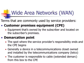
WAN vs LAN • Span • BW • Delay • Different protocols • Usually you don’t own the WAN infrastructure
Point to point link • That’s what you “see” • Ex: leased line • Usually simulated by a circuit or packet switched network
Circuit Switching • Based on the PSTN (Public Switched Telephone Network) • Analog: modems up to 56K • Digital: 64K circuits - SDH w/ TDM • cf Bocq • Designated circuits
Packet Switching • Data streams segmented in packets • Statistical Multiplexing (FIFO or QoS techniques)
Circuit vs Packet switching • Circuit: Sum of peak data rates < transmission capacity • Packet: Sum of average data rates < transmission capacity • Circuit: waste of BW • Packet: delay => unacceptable for voice
Connection oriented vs Connectionless • Circuit: CO • Data: CL => need addressing
Virtual Circuits • Connection Oriented: encapsulation includes a “flow” identifier • Best of two worlds? • Switched VCs - 3 phases: circuit setup, data transfer, circuit termination • Permanent VCs - more expensive as need to be constantly up, use less BW
SDLC • Developped by IBM for use w/ SNA • Most of L2 protocols are based on the SDLC format (HDLC, LAPB, 802.2, etc…)
X.25 • 1970s • Data Terminal Equipment (DTE) • Data Circuit-terminating Equipment (DCE) • Packet Switching Exchange (PSE) • DCE provides clock
X.25 Data Link Control • Point to point full duplex data links • Correction of errors and congestion control • Encapsulation of data in variable length frames delimited by flags • Redundant error correction bits • Sliding window (8 or 128 frames)
X.121 address • Data Network Identification Code (DNIC) • National Terminal Number (NTN)
Packet Level Protocol • Several circuits multiplexed • Sliding window error and congestion control for every VC • Call restriction, charging, QoS, ...
VC Setup • PVC: permanent entry in “routing” table (static), substitute to leased lines • SVC: dynamic entry in “routing” table triggered by an “open” packet and torn down by “close” packet
Characteristics • Introduced in 1984 but only (significantly) deployed in the late 1980s • L1 and 2 • Packet Switched technology: PVCs and SVCs • Connection-oriented data link layer communication • X.25 “lite”
Differences with X.25 • Less robust • Assumes more reliable medium => • No retransmission of lost data • No windowing • Error control handled by higher layers • Higher performance and transmission efficiency
DLCI • Data Link Connection Identifier • Uniquely identify circuits • Assigned by service provider • Local significance only (except with LMI)
Discard Eligibility • One bit in the address field • Identifies lower importance traffic that will be dropped first if congestion occurs • Set by DTE equipment
Congestion Control: FECN • FECN: Forward Explicit Congestion Notification • DCE sets FECN bit to 1 • When received by DTE, it indicates that frame experienced congestion • Sent to higher layers or ignored
Congestion Control: BECN • BECN: Backward Explicit Congestion Notification • Same as FECN but set on the return flow
LMI • Local Management Interface • Frame Relay “extension” • Introduced in 1990 by the “gang of four” (Cisco, DEC, Nortel and Stratacom) • Additional capabilities for complex internetworking environments • Later Standardized by CCITT
LMI (2) • Global addressing: DLCIs become global addresses • Virtual-circuit status messages • Multicasting
CIR • What you buy with a FR connection • Committed Information Rate • CIR= Committed Burst/Committed Time • Also Maximum Rate
ATM Asynchronous Transfer Mode
Characteristics • Originally designed to transmit voice, video and data over the same network • Cell switching • Each communication is assigned a timeslot • Timeslots are assigned on a demand-basis => asynchronous (as opposed to TDM)
Cells • 53 bytes: 5 byte header + 48 byte payload • Tradeoff between voice world and data world: • Voice needs small payloads and low delay • Data needs big payload and less overhead
ATM Interfaces • UNI: User to Network Interface • NNI: Network to Network Interface
UNI and NNI differences • NNI has bigger VPI range • UNI has Generic Flow Control field • GFC used to identify different end stations
VPI and VCI • Used to determine paths • VPI: Virtual Path Identifier • VCI: Virtual Channel Identifier • VPI identifies a bundle of VCIs
ATM Switching • Table look up • Incoming interface/VPI/VCI is mapped to an outgoing interface/VPI/VCI
ATM Adaptation Layer (AAL) • Together with ATM layer, equivalent to Data Link layer in OSI model • AAL1: Connection Oriented => Voice and Video • AAL 3,4: Connection Oriented and Connectionless (similar to SMDS) • AAL 5: Connection Oriented and Connectionless for CLIP and LANE