Download
1 / 31
310 likes | 315 Views
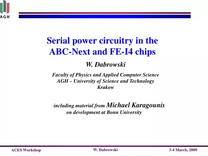
Serial power circuitry in the ABC-Next and FE-I4 chips. W. Dabrowski Faculty of Physics and Applied Computer Science AGH – University of Science and Technology Krakow. including material from Michael Karagounis on development at Bonn University. How the serial powering started.

E N D
Serial power circuitry in the ABC-Next and FE-I4 chips W.Dabrowski Faculty of Physics and Applied Computer Science AGH – University of Science and Technology Krakow including material from Michael Karagounis ondevelopment at Bonn University
How the serial powering started Critical problem of mismatchwhenconnectingsuch devices inparallelhasbeenovercome by makingrelativelylargeoutputresistance. Ultimately we need much lower output resistance and so much better regulation of the output voltage. 2
Distributed shunt regulator Power dissipated in the shunt regulators is distributed uniformly across the hybrid. No very high current devices required. Single point of failure reduced compared to one regulator per hybrid. Hybrid design fully scaleable with respect to power distribution. but …... Matching becomes critical when making the shunt regulators of low output resistance. New shunt regulator circuits suitable for integration in the readout chips have been developed independently for the strip readout and the pixel readout. 3
Serial powering in strip readout Prototype chip for Si strip readout in Upgrade Inner Tracker Binary readout Front-end optimised for short strips Positive or negative input charge Readout clock up to 160 Mbits/sec 250 nm CMOS (IBM) technology 2.5 V digital power supply (100 mA) 2.2 V analogue power supply (30 mA) Compatible with serial powering scheme 4
On chip power management and distribution • Two optional shunt regulators • Full shunt regulator in each ABCN chip • Shunt transistor in each ABCN and regulation circuitry external common for all chips on the moule • Serial voltage regulator (optional) vddd 2.5V Vdd(a) Shunt1 Regulator Shunt2 Regulator Voltage Regulator ABCN Analoge ABCN Digital 2.2V Gnd (same as Substrate) gndd On/off ShuntCtrl On/off 5
Powering-up modules Nominal powering-up scenario Supply current ramped up to the nominal required value with clock signal active in the digital part – digital switching current increase smoothly following the I-V characteristic of the digital load. Critical scenarios Clock signal is delayed with respect the power start-up – supply current forced by external current supply may temporarly go much above the ABCN current consumption. Clock signal lost suddenly during normal operation – digital current consumption suddenly reduced. 6
Full shunt regulator on chip - design concept Shunt current limiter Current limit set by an internal resistor and selected by bonding Re-ajustment and redistribution of the shunt current Number of stages depends on the assumed spraed of parameters Adjustment of the reference voltage 7
Matching problem (simulation) Clock is ON all the time 20 ABCNs with internal shunt regulators connected in parallel. All mismatch effects represented by mismatch of reference voltages. Flat distribution in a range –10 mV to +10 mV assumed. Average shunt current of 8 mA per device. One shunt device always wins This would happen even if we assumed perfect matching because of the voltage drops along the power busses on the hybrid. 8 8
Matching problem (simulation) Clock delayed Clock OFF during operation Clock ON Clock OFF 9
Performance of the auxiliary circuits (simulation) Clock is ON all the time Only current limiter active All circuitry active 10
Performance of the current limiter (measurements) Single ABCN 11
ABCN in 130 nm Design assumptions Estimate of power in ABCN130n by Mitch Newcomer Power supply voltages are not compatible with the power management schema implemented in ABCN (250 nm) assuming serial powering. 14
Possible schema of power management in ABCN (130 nm) 1 vddd 1.2 V Vddd 1.2V ABCN Analog Voltage Regulator ABCN Digital ShuntRegulator 0.9V gnd gnda Quality of analogue power supply ? Some saving of digital power due to lower voltage swing 15
Possible schema of power management in ABCN (130 nm) 2 vddd 1.8 V 0.9 V 1.2 V DC-DC Step-down /2 ShuntRegulator ABCN Digital Voltage Regulator ABCN Analog gnd gnda gnd Overhead in voltage drop in the linear regulator (loss of efficiency) No regulation on the digital power line (?) DC-DC converter 3/2 step down may improve the efficiency 16
Possible schema of power management in ABCN (130 nm) 3 vddd 0.9 V Vdd(a) 1.5V Fully integrated ShuntRegulator Voltage Regulator ABCN Analoge DC-DC Charge pump ABCN Digital 1.2V gnda gndd Design studycarried out by M. Bochenek Possibly most efficient system compatible with serial powering 17
Charge pump – design study 1.3 V transistors 2.5 V transistors 18
Power management in ABCN (130 nm) - to be done Further optimisation of the charge pump – there is a number of details to be optimised in the design (switching transistors, buffers, level shifter …. Implementation of the fully integrated shunt design from ABCN (250nm) in the 130 nm technology. Implementation of the serial regulator in 130 nm. Integration of a complete power management block to be included on the front-end prototype chip. 20
Summary Much progress has been made on understanding and development of the serial powering for both, the strip readout and the pixel readout. Fully integrated shunt regulator has been implemented in the ABC Next (250 nm) – it will allow building a large scale demonstrattor object with serial powering. A new shunt regulator design has been proposed and prototype sucessfully for the pixel readout. Optimising power efficiency may require combining serial powering with DC-DC on-chip conversion. Implementation of serial powering must be readout architecture and technology specific. 26
Implementation Shunt transitor PMOS 8000/0.3 Current comparators Sens transitor NMOS 8000/0.3 Bandgap reference Shunt amplifier Correction amplifier 28
Implementation - layout Serial regulator Shunt regulator 0.6 mm 1.5 mm 29
Ouput impedance - single shunt regulator Shunt curent of 5 to 10 mA will be required I=10mA I=5mA I=2mA For a hybrid with 20 ABCNs the effective output impedance will be about 20 times smaller 30
Current setting and control 5 modules (20 ABCNs each) in series How do we set and control the supply current? The digital current may vary substantially with occupancy (noise scan) and process variation An ”ideal” solution: the supply current of a super module is controlled based on the voltage sensing and voltage regulation at the supermodule input only, e.g. for 5 modules: 5×2.5V Implications for the overll powering system needs to be understood better 31