Download
1 / 15
200 likes | 498 Views
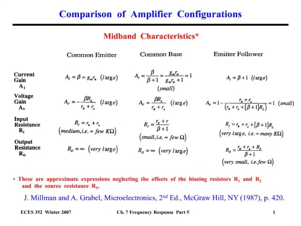
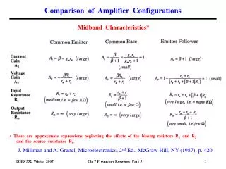
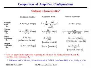
CSE598A/EE597G Spring 2006. Operational Amplifier Configurations. Jaehyun Lim, Kyusun Choi Department of Computer Science and Engineering The Pennsylvania State University. Ideal Op-Amp. infinite voltage gain (A = ∞, V - =V + for finite V O )

E N D
CSE598A/EE597G Spring 2006 Operational Amplifier Configurations Jaehyun Lim, Kyusun Choi Department of Computer Science and Engineering The Pennsylvania State University
Ideal Op-Amp • infinite voltage gain (A = ∞, V-=V+ for finite VO) • infinite input impedance (i- = i+ = 0) • zero output impedance • infinite bandwidth • zero input offset i- V- VO V+ i+ VO = A(V+ - V-)
Ideal Op-Amp • Inverting Amplifier Configuration • current through R1 = current through Rf (∵ i-=i+= 0) (Vin-V1) / R1 = (V--VO) / Rf • and V- = V+ = 0 • VO = -(Rf / R1)·Vin Rf R1 V- Vin VO
Ideal Op-Amp • Non-Inverting Amplifier Configuration • current through R1 = current through Rf (∵ i-=i+= 0) (VO-V-) / Rf = V- / R1 • and V- = V+ = Vin • VO = (1 + Rf / R1)·Vin Vin VO V- Rf R1
Ideal Op-Amp • Voltage Follower (Unit Gain Buffer) • unit-gain non-inverting amplifier • VO = Vin VO Vin
Non-Ideal Op-Amp • Real World • gain is not infinite V- ≠ V+ • gate current i+ ≠ 0, i- ≠ 0 (but still negligible) • finite bandwidth requires frequency compensation
Non-Ideal Op-Amp • Inverting Amplifier Configuration Rf R1 V- Vin VO -Rf/R1 VO = A(V+ - V-) V- = -VO / A (Vin - V-) / R1 = (V- - VO) / Rf VO = Vin 1+(1+Rf/R1)/A note that if A → ∞, VO→ -(Rf / R1)Vin
Non-Ideal Op-Amp • Non-Inverting Amplifier Configuration Vin VO V- A VO = Vin R1 Rf 1+ A R1 R1+Rf note that if A → ∞, VO→ (1+Rf / R1)Vin
Op-Amp with Single Supply • Inverting Amplifier Configuration Rf R1 Vin VO R Vdd / 2 R
Op-Amp with Single Supply • Non-Inverting Amplifier Configuration Vin VO R Vdd / 2 Rf R
Op-Amp with Single Supply • Amplifier Design • well-designed amplifier should have a transition point centered at Vdd / 2 Vdd V VO Vdd/2 VO V+ Vdd / 2 V+ V Vdd / 2
Op-Amp with Single Supply • Examples from Last Class • voltage comparator • V+ = 2.5 V VO = ? • V+ = 2.501 V VO = ? • V+ = 2.499 V VO = ? 5 V 2.5 V VO V+
Op-Amp with Single Supply • Examples from Last Class • ideal case (gain = ∞) • V+ = 2.5 V VO = 2.5 V(V+ = V- for finite VO and VO centered at 2.5 V) • V+ = 2.501 V VO = 2.5 + A(V+-V-) = ∞ VO = 5 V (limited to supply) • V+ = 2.449 V VO = 2.5 + A(V+-V-) = -∞ VO = 0 V (limited to supply) 5 V 2.5 V ∞ VO V+
Op-Amp with Single Supply • Examples from Last Class • gain A = 1000 • V+ = 2.5 V VO = 2.5 V (VO centered at 2.5 V) • V+ = 2.501 V VO = 2.5 + 1000(V+-V-) = 3.5 V • V+ = 2.449 V VO = 2.5 + 1000(V+-V-) = 1.5 V 5 V 2.5 V A VO V+
Op-Amp with Single Supply • HSpice Simulation • .DC analysis • centered at 2.5 V • gain ≈ 1,175 • V+ = 2.501 V VO = 3.421 V • V+ = 2.449 V VO = 1.324 V V+ VO