Download
1 / 28
280 likes | 429 Views
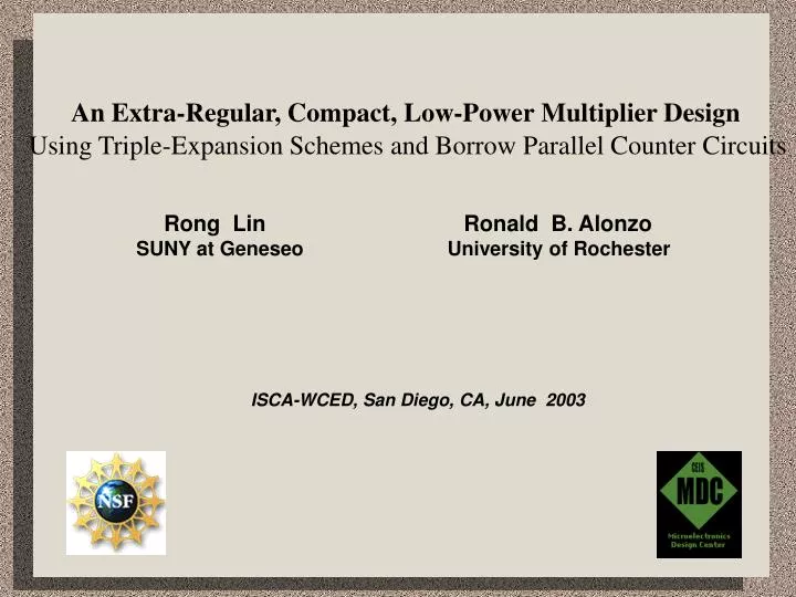
An Extra-Regular, Compact, Low-Power Multiplier Design Using Triple-Expansion Schemes and Borrow Parallel Counter Circuits. Rong Lin Ronald B. Alonzo SUNY at Geneseo University of Rochester. ISCA-WCED, San Diego, CA, June 2003.

E N D
An Extra-Regular, Compact, Low-Power Multiplier Design Using Triple-Expansion Schemes and Borrow Parallel Counter Circuits Rong Lin Ronald B. Alonzo SUNY at Geneseo University of Rochester ISCA-WCED, San Diego, CA, June 2003
The Focus of The Presentation:A Complexity-Reduced Multiplier Design Approach With superiority in layout compactness, small area, low-power, high-performance, with potential for self testability. Contents • Background • Overview of the building block circuits • Overview of the intermediate block circuits • Overview of the triple expanded multiplier architecture • Experimental work • Concluding remarks
Traditional Approach Stage 1: Generation of the large partial product bit matrix -----Usually with Booth recoding Stage 2: Reduction of the partial product matrix into two numbers ----- Usually with binary CSA adders: (3,2) (4, 2) based Stage 3: Final addition (by a standard fast adder) Recently proposed designs: Rectangular-styled Wallacetree [Ref. 2] (Itoh, et al. 2001) two groups of partial Product bits Limited switch dynamic logic [Ref.1] (Montoye, et al. 2003) merging precharged Dynamic logic into Input of every latch
Our Approach Stage 1: Generation of many (81 for 54x54-b) small partial product bit matrices in parallel -----Non-Booth Stage 2: Reduction of the partial product matrices into two numbers ----- with non-binary 4-b 1-hot encoded counters (called borrow parallel counters ), which are larger than (3,2) (4, 2) binary counters Stage 3: Final addition (by a standard fast adder) Complexity is reduced significantly: simple CMOS technology Smaller area minimal custom design repeatable and modular self-testable low-power
The building block circuits: borrow parallel counters The 5_1 borrow parallel counter
About the large parallel counter 5_1 Receiving 5 binary Input bits with 1 of them being weighted 2 (called borrow bit), and others weighted 1. Producing 2 output bits and 3 In-stage carry in and out bits), so that the weighted sums of all in bits and all out bits are equal. CMOS pass-transistor circuit processing 4-b 1-hot encoded signals, each representing an integer of value ranging 0 to 3.
(1) Low switching activity(2) Fewer hot lines (data paths)(3) Low transistor count (78; equivalent to 3.3 FA’s)
(4) A very compact layout due to good transistor distribution and 4 identical paths processed in parallel (binary logic does not have the advantages)
The borrow bit (in red) Simplify the logic, reduce the number of transistors (2) Reduce the number of pass transistors cascaded (no more than 4 including 1 within the input inverter) (3) Rearrange and balance input bits for small multipliers
The embedded full adder adding two 4-b 1-hot encoded bits (s0 at column j+2, s1 column at j+1) and 1 binary bit (q at column j) directly ------ they have the same weight! No type-conversion needed
The embedded full adder adding two 4-b 1-hot encoded bits (s0 at column j+2, s1 column at j+1) and 1 binary bit (q at column j) directly ------ they have the same weight! No type-conversion needed
The 6 x 6-b borrow parallel multiplier ovals with the same color form an embedded FA (or HA or a binary bit) (3,2): 3 ovals (2,2): 2 ovals single bit: 1 oval Input: two 6-b numbers; output two numbers: p10 - p0 and q10 - q5 CSA style output, because it serves as an intermediate block) • An array of borrow parallel counters (virtually eliminating all area needed for inter-counter connections) • The height of the block is very small (important for triple expansion) Inheriting all advantages of borrow parallel counters Delay = a single counter delay Height = a single counter height • Extra compact virtually no inter-counterconnection
Comparison of inter-block connections of 6 x6 multipliers Borrow parallel approach Traditional approach 30% area reduction!
The partial product bit matrix trisect-decomposition and first-level multiplier triple expansion Triple 6 x 6-b => 18 x 18-b multiplier
Second-level multiplier triple expansion Triple 18 x 18-b => 54 x 54-b multiplier 54 x 54-b
5. The Experimental Work: Layout And Tests
The 6 x 6 multiplier - wiring at this level very simple - Manhattan cell structure
The 4X4 multiplier with counters (4,2), (3,2), and (2,2) - wiring very irregular
Concluding Remarks Complexity-reduced multiplier design with new arithmetic circuits and schemes achieving low-power high-performance through a novel logic approach which includes: (1) 4-b 1-hot data paths are dominated (lower switching activity in each logic stage) (2)Fewer hot lines generated in logic process (power & leakage power) (3) Lower transistor count (4) Higher circuit regularity, lower layout complexity (5) Lower complexity of component interconnection
Concluding Remarks (cont’d) (6) Utilizing borrow bits for simple circuit and high speed, more importantly, reducing pass-transistor path length (no more than 4) and rearranging and balancing input bits to each column of small multipliers. (7) Utilizing partial product bit matrix decomposition for component repetition and full self-testability, achieving high observability and controllability for component circuits (small multipliers are exhaustively testable)