Download
1 / 45
490 likes | 879 Views
Low Power CMOS Design. Vishwani D. Agrawal James J. Danaher Professor ECE Dept., Auburn University, Auburn, AL 36849 www.eng.auburn.edu/~vagrawal 23 rd International Conference on VLSI Design Education Forum, January 7, 2010 Bangalore, India. CMOS Logic (Inverter).

E N D
Low Power CMOS Design Vishwani D. Agrawal James J. Danaher Professor ECE Dept., Auburn University, Auburn, AL 36849 www.eng.auburn.edu/~vagrawal 23rd International Conference on VLSI Design Education Forum, January 7, 2010 Bangalore, India Agrawal: Low Power CMOS Design
CMOS Logic (Inverter) No static leakage path exists for either 1 or 0 input. F. M. Wanlass and C. T. Sah, “Nanowatt Logic using Field-Effect Metal-Oxide-Semiconductor Triodes,” IEEE International Solid-State Circuits Conference Digest, vol. IV, February 1963, pp. 32-33. Agrawal: Low Power CMOS Design
Power of a CMOS Gate Transition VDD Dynamic Power = CLVDD2/2+ Psc Static power = VDD Ileakage R Vo Vi CL R isc Ground Agrawal: Low Power CMOS Design
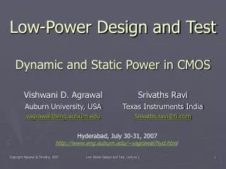
Power Consumption of VLSI Chips Why is it a concern? Agrawal: Low Power CMOS Design
ISSCC Keynote, Feb. 2001 “Ten years from now, microprocessors will run at 10GHz to 30GHz and be capable of processing 1 trillion operations per second – about the same number of calculations that the world's fastest supercomputer can perform now. “Unfortunately, if nothing changes these chips will produce as much heat, for their proportional size, as a nuclear reactor. . . .” Patrick P. Gelsinger Senior Vice PresidentGeneral Manager Digital Enterprise Group INTEL CORP. Agrawal: Low Power CMOS Design
10000 1000 Rocket Nozzle 100 Nuclear Power Density (W/cm2) Reactor 8086 10 4004 P6 8008 Pentium® 8085 386 286 486 8080 1 1970 1980 1990 2000 2010 Year VLSI Chip Power Density Sun’s Surface Hot Plate Source: Intel Agrawal: Low Power CMOS Design
Low-Power Design • Design practices that reduce power consumption by at least one order of magnitude; in practice 50% reduction is often acceptable. • Low-power design methods: • Algorithms and architectures • High-level and software techniques • Gate and circuit-level methods • Test power Agrawal: Low Power CMOS Design
Components of Power • Dynamic Power • Signal transitions • Logic activity • Glitches • Short-circuit • Static Power • Leakage Ptotal = Pdyn + Pstat = Ptran +Psc+Pstat Then = Ptran +Psc+ Pstat Now Agrawal: Low Power CMOS Design
Dynamic Power • Each transition of a gate consumes CV 2/2. • Methods of power saving: • Minimize load capacitances • Transistor sizing • Reduce transitions • Logic design • Glitch reduction Agrawal: Low Power CMOS Design
Glitch Power Reduction • Design a digital circuit for minimum transient energy consumption by eliminating hazards Total transitions = 6 Essential transitions = 2 Glitch transitions = 4 Agrawal: Low Power CMOS Design
Multi-Input Gate A B Delay D < DPD DPD: Differential path delay C A B C DPD D D Hazard or glitch time Agrawal: Low Power CMOS Design
Balanced Path Delays A B Delay D < DPD DPD C Delay buffer A B C D No glitch time Agrawal: Low Power CMOS Design
Glitch Filtering by Inertia A B Delay D> DPD C A B C DPD D > DPD Filtered glitch time Agrawal: Low Power CMOS Design
Designing a Glitch-Free Circuit • Maintain specified critical path delay. • Glitch suppressed at all gates by • Path delay balancing • Glitch filtering by increasing inertial delay of gates or by inserting delay buffers when necessary. • A linear program optimally combines all objectives. Path delay = d1 Delay D Path delay = d2 Minimum transient energy condition: |d1 – d2| < D Agrawal: Low Power CMOS Design
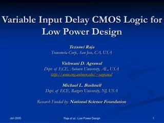
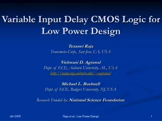
Linear Program (LP) • Variables: gate and buffer delays, arrival time variables. • Objective: minimize number of delay buffers. • Subject to: overall circuit delay constraint for all input-output paths. • Subject to: minimum transient energy condition for all multi-input gates. • Reference: T. Raja, V. D. Agrawal and M. L. Bushnell, “Variable Input Delay CMOS Logic for Low Power Design,” IEEE Trans. CAD, vol. 17, no. 10, pp. 1534-1545, Oct. 2009. Agrawal: Low Power CMOS Design
An Example: Full Adder 1 1 1 1 1 1 1 1 1 Critical path delay = 6 Agrawal: Low Power CMOS Design
LP Step 1: Define Varaibles • Gate delay variables: d4 . . . d12 • Buffer delay variables: d15 . . . d29 • Arrival time variables (earliest): t4 . . . T29 • (longest): T4 . . . . T29 Agrawal: Low Power CMOS Design
LP Step 2: Specify Constraints For Gate 7: T7≥ T5 + d7 t7≤ t5 + d7 d7 > T7 - t7 T7≥ T6 + d7 t7≤ t6 + d7 Agrawal: Low Power CMOS Design
LP Step 2 (Cont.) Buffer 19: T16 + d19 = T19 t16 + d19 = t19 Agrawal: Low Power CMOS Design
LP Step 2: Critical Path Constraints T11≤maxdelay T12≤maxdelay maxdelay is specified Agrawal: Low Power CMOS Design
LP Step 3: Define Objective Function • Need to minimize the number of buffers. • Because that leads to a nonlinear objective function, we use an approximate criterion: minimize ∑ (all buffer delays) i.e., minimize d15 + d16 + ∙ ∙ ∙ + d29 • This gives near optimum results. Agrawal: Low Power CMOS Design
LP Solution: maxdelay =6 1 2 1 1 1 1 1 2 1 2 2 Critical path delay = 6 Agrawal: Low Power CMOS Design
LP Solution: maxdelay =7 3 1 1 1 1 1 2 2 1 2 Critical path delay = 7 Agrawal: Low Power CMOS Design
LP Solution: maxdelay ≥11 5 1 1 1 3 1 2 3 4 Critical path delay = 11 Agrawal: Low Power CMOS Design
ALU4: Original and Glitch-Free Agrawal: Low Power CMOS Design
C7552 Circuit: Spice Simulation Power Saving: Average 58%, Peak 68% Agrawal: Low Power CMOS Design
Components of Power • Dynamic Power • Signal transitions • Logic activity • Glitches • Short-circuit • Static Power • Leakage Agrawal: Low Power CMOS Design
Leakage Reduction Problem 65nm CMOS technology: Low threshold transistors, gate delay 5ps, leakage current 10nA. High threshold transistors, gate delay 12ps, leakage 1nA. Minimize leakage current without increasing critical path delay. What is the percentage reduction in leakage power? What will be leakage power reduction if 30% critical path delay increase is allowed? Agrawal: Low Power CMOS Design
Solution 1: No Delay Increase Reduction in leakage power = 1 – (4×1+7×10)/(11×10) = 32.73% Critical path delay = 25ps 12ps 5ps 12ps 5ps 5ps 5ps 5ps 5ps 12ps 5ps 12ps Agrawal: Low Power CMOS Design
Solution 2: 30% Delay Increase Several solutions are possible. Notice that any 3-gate path can have 2 high threshold gates. Four and five gate paths can have only one high threshold gate. One solution is shown in the figure below where six high threshold gates are shown with shading and the critical path is shown by a dashed red line arrow. Reduction in leakage power = 1 – (6×1+5×10)/(11×10) = 49.09% Critical path delay = 29ps 5ps 12ps 5ps 12ps 5ps 12ps 12ps 5ps 12ps 5ps 12ps Agrawal: Low Power CMOS Design
Integer Linear Programming (ILP) to Minimize Leakage Power • Assign every gate i an integer [0,1] variable Xi. • Define ILP constraints for critical path delay. • Define objective function to minimize total leakage. • Let ILP find values of Xi’s: If Xi = 1, assign low threshold to gate i If Xi = 0, assign high threshold to gate i Agrawal: Low Power CMOS Design
Power-Delay Tradeoff Agrawal: Low Power CMOS Design
Leakage & Dynamic Power Optimization 70nm CMOS c7552 Benchmark Circuit @ 90oC Leakage exceeds dynamic power Y. Lu and V. D. Agrawal, “CMOS Leakage and Glitch Minimization for Power-Performance Tradeoff,” Journal of Low Power Electronics (JOLPE), vol. 2, no. 3, pp. 378-387, December 2006. Agrawal: Low Power CMOS Design
Power Constrained Test Scheduling R1 R2 M1 M2 R3 R4 A datapath Agrawal: Low Power CMOS Design
Minimum Test Time LFSR1 LFSR2 T2: test for M2 M2 M1 Test power T1: test for M1 MISR1 MISR2 Test time Agrawal: Low Power CMOS Design
Minimum Test Power R1 LFSR2 M2 M1 Test power T1: test for M1 T2: test for M2 MISR1 MISR2 Test time Agrawal: Low Power CMOS Design
Testing of MCM and SOC • Test resources: Typically registers and multiplexers that can be reconfigured as test pattern generators (e.g., LFSR) or as output response analyzers (e.g., MISR). • Test resources (R1, . . .) and tests (T1, . . .) are identified for the system to be tested. • Each test is characterized for test time, power dissipation and resources it requires. Agrawal: Low Power CMOS Design
Resource Allocation Graph(A Bipartite Graph) T1 T2 T3 T4 T5 T6 R1 R2 R3 R4 R5 R6 R7 R8 R9 Reference: R. M. Chou, K. K. Saluja and V. D. Agrawal, “Scheduling Tests for VLSI Systems Under Power Constraints,” IEEE Trans. VLSI Systems, vol. 5, no. 2, pp. 175-185, June 1997. Agrawal: Low Power CMOS Design
Test Compatibility Graph (TCG) T1 (2, 100) T6 (1, 100) T2 (1,10) T5 (2, 10) T3 (1, 10) T4 (1, 5) Power Test time Tests that form a clique can be performed concurrently (test session) Pmax = 4 Agrawal: Low Power CMOS Design
Find All Cliques in TCG Agrawal: Low Power CMOS Design
Integer Linear Program (ILP) • For each clique (test session) i, define: • Integer variable, xi = 1, test session selected, or xi = 0, test session not selected. • Constants, Li = test length, Pi = power. • Constraints to cover all tests: • T1 is covered if x1 + x2 + x3 + x4 + x5 + x6 + x11 ≥ 1 • Similar constraint for each test, Tk • Constraints for power: Pi × xi ≤ Pmax Agrawal: Low Power CMOS Design
ILP Objective and Solution • Objective function: • Minimize Σ Li × xi all cliques • Solution: • x3 = x8 = x10 = 1, all other xi’s are 0 • Test session 3 includes T1 and T6 • Test session 8 includes T2 and T5 • Test session 10 includes T3 and T4 • Test length = L3 + L8 + L10 = 120 • Peak power = max {P3, P8, P10} = 3 (Pmax = 4) Agrawal: Low Power CMOS Design
Summary • Underlying theme in our research – use of mathematical optimization methods for power reduction at gate level: • Dynamic power • Leakage power • Power minimization under process variation • Test power • Other research • Min-max power estimation • Architecture level power management • Software, instruction set • Multicore Agrawal: Low Power CMOS Design
Research Students • T. Raja, MS 2002, PhD 2004 (NVIDIA) • S. Uppalapati, MS 2004 (Intel) • F. Hu, PhD 2006 (Intel) • Y. Lu, PhD 2007 (Intel) • J. D. Alexander, MS 2008 (Texas Instruments) • K. Sheth, MS 2008 • M. Allani, PhD • J. Yao, PhD • K. Kim, PhD • M. Kulkarni, MS Agrawal: Low Power CMOS Design
Dissertations and Papers • Dissertations: http://www.eng.auburn.edu/~vagrawal/THESIS/thesis.html • Papers: http://www.eng.auburn.edu/~vagrawal/TALKS/talks.html Agrawal: Low Power CMOS Design