Download
1 / 55
550 likes | 651 Views
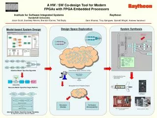
Virtex II-Pro Dynamical Test Application - Part B -. Performed By: Khaskin Luba Einhorn Raziel Instructor: Rivkin Ina Winter 2005. Quick Overview. Examining possible space-compatibility of civilian devices , in order to integrate them in satellites.

E N D
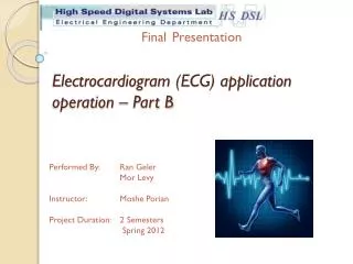
Virtex II-Pro Dynamical Test Application- Part B - Performed By: Khaskin Luba Einhorn Raziel Instructor: Rivkin Ina Winter 2005
Quick Overview • Examining possible space-compatibility of civilian devices, in order to integrate them in satellites. • Statistically modelingthe device’s robustness to temporary damage and it’s ability to recover in a case of an error. • Testing the device’s modules functioning under real-time radiation.
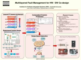
Serial Port USB Port JTAG Port DUT -Virtex II-PRO XC2VP7 (placed on the development board) HOST - PC THE COMPLETE SYSTEM OVERVIEW
Host GUI Xilinx Tools Microsoft Excel USB Port JTAG Port Serial Port DUT Virtex II-PRO FPGA Logic Power PC System Block Diagram
Host DUT The Virtex II-PRO FPGA XC2VP7 The Internal FPGA Modules: - 8 Rocket I/O Transceiver Blocks - 4 DCM (Digital Clock Manager) - 44 Block Select RAM Memory total of 792KB - 44 18x18 Multiplier Blocks - PPC405 - 396 User I/O pads - 4928 slices holding 157KB memory, 9856 flip-flops, and 11088 logic cells
Host DUT Graphical User Interface • User transparent • Initializing the testing system • Choosing and loading the testing function • Receiving data via USB and calculating statistical results • GUI was created in C++ language, using Visual Studio 6 • Uses supplied Dynamic Library files (Dll files), in order to control the USB module
Host DUT Writing appropriate impl. file Opening USB port Sending start signal Gathering test info Test type decision START End Test condition Opening Excel Closing USB port Delete temporary var. Listening to USB Collecting data to Excel file Test Ended Test in Process Graphical User Interface - Algorithm
Host DUT GUI – Main Window Test Type Tests List Status Window
Host DUT GUI – Settings Window Serial Port COM Select Programs’ location USB connection & drivers check button
The DUT Host Host JTAG Port JTAG Port USB Port Serial Port DUT -Virtex II-PRO FPGA LOGIC DUT -Virtex II-PRO FPGA Power PC Combined of: • Power PC • Logic– logic and memory elements, DCM, MGT. In the Power PC tests the Serial Port is being used. In the Logic tests the USB Port is being used. The first part of this presentation deals with the LOGIC modules of the FPGA and the USB connection…
Host DUT DLP-USB245M - Features • Fast connection – up to 1 Mb/sec. • Small implementation • Simple Interface • Mounted on a P130 expansion module
MCT USB Contr. MUT MUT - Module Under Test The examined modules: • I/O Blocks • Fast Multipliers • Rocket I/O • Digital Clock Manager (DCM) • CLB Memory • CLB Flop-flops • CLB logic • BRAMs • Power PC
MCT USB Contr. MUT USB Controller • Controls reading and writing cycles. • Determines USB’s control signals during reading and writing cycles. • Sets up the relevant data to be sent back to host. • Designed with minimal usage of logic and memory elements.
MCT USB Contr. MUT USB Controller
MCT USB Contr. MUT MCT • Identical basic structure for all the testing functions: - Defines input and comparison vectors in order to test the module’s functioning. - Computes the numbers of errors and instructs their transference using the USB Controller. • Designed with the ambition to maximize the test’s mapping of each examined module. • Minimal usage of logic and memory elements.
Creating input and comparison vectors; Updating control signals Loading bit file Waiting for outputs Sending input vectors to MUT Checking outputs; Sending results Single/ Multiple tests? Listening to Host Multiple tests End Test Command Single test Test Ended The MCT Testing Flow
The Fast Multipliers Test Reading Control MCT Reset Block Read-Write Control MCT USB Contr. MUT Error Generator * Indicator USB Controller Writing Control MUT (Multiplier Blocks)
MCT USB Contr. MUT The Fast Multipliers Test • Several blocks of fast multipliers are chained together to achieve 100% mapping. • The input vectors, set by the MCT, diffuse through the multipliers chain. The outputs are being compared with the expected result vectors using several feedbacks. • The calculated errors are being sent via USB, using the USB Controller, in steady time intervals. • Same method of diffusion through the MUT blocks chain and of error calculation by comparison between the expected result vectors and the output vectors was used in all the performed tests described further…
Fast Multipliers Test Mapping Statistics: Design Summary -------------- Number of errors: 0 Number of warnings: 0 Logic Utilization: Number of Slice Flip Flops: 1,229 out of 9,856 12% Number of 4 input LUTs: 1,796 out of 9,856 18% Logic Distribution: Number of occupied Slices: 1,352 out of 4,928 27% Total Number 4 input LUTs: 1,820 out of 9,856 18% Number of bonded IOBs: 13 out of 248 5% Number of PPC405s: 0 out of 1 0% Number of MULT18X18s: 44 out of 44 100% Number of GCLKs: 1 out of 16 6% Number of GTs: 0 out of 8 0% Number of GT10s: 0 out of 0 0%
The BRAMs Test Reading Control MCT Reset Block Read-Write Control MCT USB Contr. MUT Indicator MUT (BRAM Block) USB Controller Writing Control
BRAMs Test Mapping Statistics: Design Summary -------------- Number of errors: 0 Number of warnings: 0 Logic Utilization: Number of Slice Flip Flops: 150 out of 9,856 1% Number of 4 input LUTs: 405 out of 9,856 4% Logic Distribution: Number of occupied Slices: 245 out of 4,928 4% Total Number 4 input LUTs: 420 out of 9,856 4% Number of bonded IOBs: 18 out of 248 7% Number of PPC405s: 0 out of 1 0% Number of Block RAMs: 44 out of 44 100% Number of GCLKs: 1 out of 16 6% Number of GTs: 0 out of 8 0% Number of GT10s: 0 out of 0 0%
CLB Flip-Flops Test MCT USB Contr. MUT MCT Reset Block Indicator MUT (CLB Flip-Flops Blocks) USB Controller
CLB Flip-Flops Test CLB Flip-Flops Block – Closer Look MCT USB Contr. MUT
CLB Flip-FlopsTest Mapping Statistics: Design Summary -------------- Number of errors: 0 Number of warnings: 0 Logic Utilization: Number of Slice Flip Flops: 9,235 out of 9,856 93% Number of 4 input LUTs: 227 out of 9,856 2% Logic Distribution: Number of occupied Slices: 4,926 out of 4,928 99% Total Number 4 input LUTs: 237 out of 9,856 2% Number of bonded IOBs: 18 out of 248 7% Number of PPC405s: 0 out of 1 0% Number of GCLKs: 1 out of 16 6% Number of GTs: 0 out of 8 0% Number of GT10s: 0 out of 0 0%
CLB Logic Test Reset Block MCT Reading Control MCT USB Contr. MUT Read-Write Control Indicator MUT (Logic Blocks - Adders) USB Controller Writing Control
CLB LogicTest Mapping Statistics: Design Summary -------------- Number of errors: 0 Number of warnings: 0 Logic Utilization: Number of Slice Flip Flops: 9,705 out of 9,856 98% Number of 4 input LUTs: 6,188 out of 9,856 62% Logic Distribution: Number of occupied Slices: 4,926 out of 4,928 99% Total Number 4 input LUTs: 6,188 out of 9,856 62% Number of bonded IOBs: 18 out of 248 7% Number of PPC405s: 0 out of 1 0% Number of GCLKs: 1 out of 16 6% Number of GTs: 0 out of 8 0% Number of GT10s: 0 out of 0 0%
CLB Memory Test Reset Block MCT MCT USB Contr. MUT Indicator MUT (LUT Blocks) USB Controller
CLB MemoryTest Mapping Statistics: Design Summary -------------- Number of errors: 0 Number of warnings: 0 Logic Utilization: Number of Slice Flip Flops: 128 out of 9,856 1% Number of 4 input LUTs: 1,047 out of 9,856 10% Logic Distribution: Number of occupied Slices: 4,920 out of 4,928 99% Total Number 4 input LUTs: 9,760 out of 9,856 99% Number used for 32x1 RAMs: 8,704 (Two LUTs used per 32x1 RAM) Number of bonded IOBs: 18 out of 248 7% Number of PPC405s: 0 out of 1 0% Number of GCLKs: 1 out of 16 6% Number of GTs: 0 out of 8 0% Number of GT10s: 0 out of 0 0%
DCM Test MCT MCT USB Contr. MUT Reset Block Indicator MUT (4 DCM Units) USB Controller
DCMTest Mapping Statistics: Design Summary -------------- Number of errors: 0 Number of warnings: 0 Logic Utilization: Number of Slice Flip Flops: 272 out of 9,856 2% Number of 4 input LUTs: 452 out of 9,856 4% Logic Distribution: Number of occupied Slices: 273 out of 4,928 5% Total Number 4 input LUTs: 452 out of 9,856 4% Number of bonded IOBs: 18 out of 248 7% Number of PPC405s: 0 out of 1 0% Number of GCLKs: 16 out of 16 100% Number of DCMs: 4 out of 4 100% Number of GTs: 0 out of 8 0% Number of GT10s: 0 out of 0 0%
Rocket I/O Test MCT Clock Buffers Reset Block MCT USB Contr. MUT Indicator MUT (Transceivers Block) USB Controller
Rocket I/O Test MCT USB Contr. MUT DATA FLOW CHART –Transceivers and Loop-back Testing
Rocket I/O Transceivers Test Mapping Statistics: Design Summary -------------- Number of errors: 0 Number of warnings: 0 Logic Utilization: Number of Slice Flip Flops: 117 out of 9,856 1% Number of 4 input LUTs: 294 out of 9,856 2% Logic Distribution: Number of occupied Slices: 186 out of 4,928 3% Total Number 4 input LUTs: 294 out of 9,856 2% Number of bonded IOBs: 26 out of 248 10% Number of PPC405s: 0 out of 1 0% Number of GTIPADs: 8 out of 16 50% Number of GTOPADs: 8 out of 16 50% Number of GCLKs: 1 out of 16 6% Number of GTs: 4 out of 8 50% Number of GT10s: 0 out of 0 0%
Rocket I/OLoop-BackTest Mapping Statistics: Design Summary -------------- Number of errors: 0 Number of warnings: 0 Logic Utilization: Number of Slice Flip Flops: 119 out of 9,856 1% Number of 4 input LUTs: 389 out of 9,856 3% Logic Distribution: Number of occupied Slices: 229 out of 4,928 4% Total Number 4 input LUTs: 389 out of 9,856 3% Number of bonded IOBs: 26 out of 248 10% Number of PPC405s: 0 out of 1 0% Number of GTIPADs: 16 out of 16 100% Number of GTOPADs: 16 out of 16 100% Number of GCLKs: 1 out of 16 6% Number of GTs: 8 out of 8 100% Number of GT10s: 0 out of 0 0%
Combined Test MCT CLB Logic (adders) DCM BRAMs MCT USB Contr. MUT Reset Block Reading Control Read-Write Control CLB Memory (LUTs) MGT Fast Multipliers Indicator USB Controller Writing Control
CombinedTest Mapping Statistics: Design Summary -------------- Number of errors: 0 Number of warnings: 0 Logic Utilization: Number of Slice Flip Flops: 8,661 out of 9,856 87% Number of 4 input LUTs: 7,137 out of 9,856 72% Logic Distribution: Number of occupied Slices: 4,926 out of 4,928 99% Total Number 4 input LUTs: 7,655 out of 9,856 77% Number of bonded IOBs: 26 out of 248 10% Number of PPC405s: 0 out of 1 0% Number of GTIPADs: 16 out of 16 100% Number of GTOPADs: 16 out of 16 100% Number of Block RAMs: 44 out of 44 100% Number of MULT18X18s: 44 out of 44 100% Number of GCLKs: 1 out of 16 6% Number of GTs: 8 out of 8 100% Number of DCMs: 1 out of 4 25% Number of GT10s: 0 out of 0 0%
SOFTWARE WORK FLOW Core Generator, Architecture Wizard Test Algorithm High Level Design Logic Simulation Low Level Synthesis Place and Route Bit file GUI Design
Host DUT The Virtex II-Pro FPGA XC2VP7Power-PC 405 structure
Performed Tests • General Purpose Registers test • MMU test (TLB) • Instruction test (including memory test) • Cache test • Timers test • Interrupts test • Integrated modules test
Test Concept - PPC • Hardware Design: 3 Hardware platforms: • Platform without access to external memory – for cache test • Platform with maximum modules – for integrated modules test • Platform with minimum modules – for all other tests • Software design: 2 layers - C code & assembly • Implementation of software in designated BRAM block
PLB OPB PPC 405 Timer BRAM JTAG RS232 (UART) To Host BRAM DCM PLB2OPB Hardware Design – Block Diagram
PLB OPB PPC 405 Timer BRAM JTAG RS232 (UART) To Host BRAM DCM PLB2OPB Hardware Design – Block DiagramCache test system
GPIO Hardware Design – Block DiagramIntegrated test system PLB OPB PPC 405 Timer BRAM JTAG RS232 (UART) To Host BRAM DCM PLB2OPB
Test Algorithm - PPC START C code Layer Create Input & “Golden” Vectors Single/ Multiple tests? FINISH TEST Assign Physical Address To inputs Load & Compare Outputs with golden vectors Send results to serial port Assembly Layer Save output Vectors to specified Physical address Load input Vectors by physical address Perform Test Create Outputs
1. General-Purpose Registers Write the following values to registers: 0x00000000,0xFFFFFFFF,0xAAAAAAAA,0x55555555, Number of register (0-31). Read from registers and compare to written values Instructions Used: li, mr, addi
2. MMU Test - TLB TLB buffer contains 64 indexes. Using same method as in the General-Purpose Registers test for the TLB Buffer. Write & read to each index Instructions Used: tlbre, tlbwe
3. Instruction Set Executing selected instructions (including memory instructions) using above values. Compare outputs with those expected. Instructions tested: Arithmetic: Add, mulli, subf Compare: cmpi, mfcr Logic: Or, And, Xor Memory: stw, lwz Branch: b
4. Cache Test As mentioned – a separate hardware platform is used here. Run simple code which performs Add, Multiply and Condition operations. Compare with expected results. • C-Code level only. No special instructions used.
5. Timers test Implement a timer (using base system resources), and Measure a pre-defined process. Compare with expected results. • C-Code level only. No special instructions used. access to timer using supplied driver.