Download
1 / 78
780 likes | 904 Views
Virtex II Pro based SoPC design. Part 1 Introduction. Before we start …. The guidance consists of two parts: Introduction SoPC concept Working platforms Design Flow – building basic system Advanced topics Adding user cores Debug (ChipScope) JTAG Simulation. Today. Outline.

E N D
Virtex II Pro based SoPC design Part 1 Introduction
Before we start… • The guidance consists of two parts: • Introduction • SoPC concept • Working platforms • Design Flow – building basic system • Advanced topics • Adding user cores • Debug (ChipScope) • JTAG • Simulation Today
Outline • SoPC design concept • SoPC platform • Memec design board • ML310 design board • Virtex II Pro Architecture • PPC architecture • Processor Buses • SoPC implementation flow
Part 1 Introduction and SoPC platform
System evolution Components of the system reside on single chip. On-chip interconnect System complexity and density All components reside in relatively small box. On-board interconnect Components of the system are large. “In-room” interconnect We are here Time Old systems Recent systems Modern systems
SoC glossary • IP (Intellectual Property) – In integrated circuits, predefined large functions, called “cores”, that help the user complete a large design faster • Soft IP (soft core) – A synthesizable IP which can be readily incorporated into an FPGA • Hard IP (hard core) – An IP which placed on FPGA during fabrication process and resides there all the time
SoC design process Choose chip with required hard cores inside Add required soft cores Add user logic
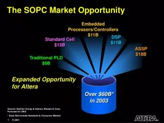
SoC platform System on Chip System On Programmable Chip System On Chip Application Specific Integrated Circuit Field Programmable Gate Array We are here
SoPC platform - inside • Virtex II Pro FPGA (XC2VP7) • ~1M ASIC gates • 44 18x18-bit Multipliers • 88 KB of on-chip memory • Power PC 4.05 CPU core • 4 2.5Gbps Rocket I/O transceivers • 4 DCM (digital clock manager) units • There are more power configurations
SoPC platform - outside • Virtex II Pro FPGA resides on Memec Development board, including: • 32 MB of SDRAM • 100MHz & 125 MHz clocks • 2x16 LCD panel • 8 user DIP switches • 4 user leds • 4 user push buttons • Serial port interface • JTAG port • Hardware debugger port • Extension to P160 card
SoPC platform - outside • P160 communication card includes, in addition to resources available on board: • 8M of Flash memory • 1M of SRAM memory • Ethernet 10/100 port • USB port • Additional serial port • PS / 2 port • External LCD interface
Configurable logic block (CLB) Virtex II Pro architecture overview
Virtex II Pro architecture overview Configurable logic block (CLB) Input Output Block (IOB)
Virtex II Pro architecture overview Configurable logic block (CLB) Input Output Block (IOB) 18 Kb Block RAM
Virtex II Pro architecture overview Configurable logic block (CLB) Input Output Block (IOB) 18 Kb Block RAM 18x18 bit multiplier
Virtex II Pro architecture overview Configurable logic block (CLB) Input Output Block (IOB) 18 Kb Block RAM 18x18 bit multiplier 2.5 Gbps Rocket I/O transceiver
Virtex II Pro architecture overview Configurable logic block (CLB) Input Output Block (IOB) 18 Kb Block RAM 18x18 bit multiplier 2.5 Gbps Rocket I/O transceiver Digital Clock Manager (DCM)
Virtex II Pro architecture overview Configurable logic block (CLB) Input Output Block (IOB) 18 Kb Block RAM 18x18 bit multiplier 2.5 Gbps Rocket I/O transceiver Digital Clock Manager (DCM) Power PC CPU core
Virtex II Pro architecture overview Configurable logic block (CLB) Input Output Block (IOB) 18 Kb Block RAM 18x18 bit multiplier 2.5 Gbps Rocket I/O transceiver Digital Clock Manager (DCM) Processor block Global and local routing
DIA DIPA ADDRA WEA WNA SSRA DOA CLKA DOPA DIB DIPB ADDRB WEB ENB SSRB DOB CLKB DOPB Block SelectRAM+ (BRAM) • 44 blocks of 18 Kb each • True dual-port RAM • Fully synchronous • Parity bits can be used • Possible configurations:
CPU-FPGA interfaces BRAM BRAM Control Logic 405 Core OCM controller OCM Controller FPGA CLB Array Interface Logic BRAM BRAM Processor Block = CPU core + Interface Logic + CPU-FPGA interface Processor block overview
On-chip Memory (OCM) Controller • OCM controller is designed to provide very quick access to a fixed amount of instruction and data memory space • OCM controller is of a distributed style and it is split into 2 blocks • Instruction Side OCM (ISOCM) • Data side OCM (DSOCM) • Instruction Side OCM: • 64-bit read only bus (two instructions per cycle) • Can support 128 KB of BRAM (if available on FPGA) • Writing to ISBRAM during BRAM initialization only • Data Side OCM: • 32-bit data read and 32-bit data write buses • Can support 64 KB of BRAM (if available on FPGA) • Writing to DSBRAM during BRAM init, by CPU, FPGA via second port • OCM is not cacheable memory !
405 Core Soft IP in Fabric I Side Controller D Side Controller BRAM BRAM Instruction Side BRAM: • Boot code • Interrupt Service Routines • Deterministic low latency Data Side BRAM: • Transient data storage • Bi-directional data transfer • Packet Processing On-chip Memory (OCM) Controller Fixed Logic
PPC 405 Core organization • 5-stage pipeline • Fetch • Decode • Execute • Write-back • Load write-back • Memory Management Unit • Separate Instruction and Data cache units • Debug support, including a JTAG interface • Three programmable timers
PPC 405 Core parts - CPU • 5-stage pipeline • 3-element fetch queue : 2 prefetch buffers + decode buffer • Static branch prediction • Execution unit consist of GPR, MAC and ALU • 32 32-bit registers with 3 read and 2 write ports • Floating point operations are not supported! • Single-cycle throughput in MAC instructions
PPC 405 Core parts - Interrupts • Critical and non critical interrupts are supported • Caused by: • Error conditions • Internal timers • Debug events • External interrupt controller (EIC) interface • 2 EIC interrupts are supported
PPC 405 Core parts - MMU • 4 GB of flat address space • Multiple page sizes supported • 1KB to 16MB pages (8 types) • Software controlled • 64 entries fully associative TLB • Software controlled • Storage attributes are provided to control access of memory regions
PPC 405 Core parts - Caches • Independent instruction and data caches • 16-KB, 2-way set associative, 32 byte line • Non-blocking caches • LRU replacement policy • Write through / write back DCU • Both have PLB master interface
PPC 405 Core parts – Debug • Four debug modes • Internal-debug : software debuggers • External-debug : JTAG debuggers • Debug-wait : interrupt servicing during processor appears to be stopped • Real-time trace : instruction trace tools • JTAG debug interface
SoPC architecture • Our SoPC based on CoreConnect standart
CoreConnect bus architecture • Processor Local Bus (PLB) • 32-bit address, 64-bit data • Separate read and write buses • High performance • Low load • On-Chip peripheral bus (OPB) • 32-bit address, 32-bit data • Max peripherals • High load • Device Control Register bus (DCR) • 32-bit transfer to and from GPR • Direct accessible by PPC
The PLB and OPB buses • The PLB can be thought of as the “Motorway” of the CoreConnect bus structure • The PLB is fast and has a very high bandwidth • There is a direct connection to the processor from the PLB • The OPB can be thought of as the “A Road” of CoreConnect • The OPB is a lower bandwidth bus designed to accommodate the needs of slower peripherals (UARTS, GPIO, etc.) • Use of the OPB allows the PLB to remain free of the slower traffic and thus work more effectively • There is no connection to PPC from the OPB • The two buses are connected by an “OPB Bridge”– just like a motorway junction
The DCR bus • The DCR bus in not used to carry any sort of data which can be processed by the execution units, nor does it carry instructions • DCRs (the registers themselves, not the bus) can be thought of as “flags”. These flags can be set to define the operating mode for processor peripherals. • E.g. criticality of interrupts, DMA channel control, UART communication modes etc. • DCR registers exist outside of the core, so the DCR bus is used to communicate with with registers
Processor block interfaces • The processor block provides I/O signals grouped functionally into the following interfaces: • PLB interface • 32-bit address and three 64-bit data buses • DCR interface • Attachment of on-chip registers for device control • Clock and Power Management (CPM) • JTAG port • Debugging • On-chip interrupt controller • Critical and non-critical interrupts • On-chip memory controller • Reset interface • Three types of reset
Part 2 SoPC design using XILINX Tools
Hardware / Software flow • How is Embedded system created? • Hardware design flow • Software design flow • Integration • Embedded development Kit (EDK) • Assists in creating system hardware definition • Calls XILINX ISE for FPGA implementation • Assists in creation of software code • GNU Cross Compiler / Debugger (GCC / GDB) • XILINX Microprocessor Debugger (XMD)
SoPC Design Tool Chain Standard Hardware Flow Standard Software Flow VHDL / Verilog C/C++ code Simulator Compiler / Linker Synthesizer Object code Place & Route .elf .bit Data2BRAM PPC code in on-chip memory PPC code in off-chip memory Download to FPGA Debugger Download to FPGA Chip Scope Pro Tools
EDK ISE Where does EDK assist? Software Flow Hardware Flow SW flow chart HW Block diagram Create SW source HW description Compile Synthesize, P&R DATA2BRAM Elf file / download Bit file / download Design Debug (HW and SW)
Using BSB to create new project Base System Builder is wizard helping you build system in easy way
Project directory structure Must be without spaces Projects directory name Current project name This directory will typically contain user c and h files code Here ucf (user constraint file) resides data User defined cores should be placed here pcores • Additional directories are created after synthesis Drivers for user defined cores should be placed here drivers Files needed for simulation sim Here will be compiled and linked code (elf) ppc405 code include Files generated during software flow lib
EDK main window System block diagram System description Message window
System description System cores Main files
EDK- Hardware flow Specify processor, bus and peripherals, hardware configuration Automatic HDL files generation Xilinx implementation flow Bitstream Download to FPGA
Specify cores Choose core version Address space must be specified if needed
Specify buses Specifying master / slave interface on the bus(es) Specifying BRAM port