Download
1 / 18
180 likes | 303 Views
DESIGN, INSTALLATION AND PERFORMANCE OF THE NEW INSULATOR FOR NSTX CHI EXPERIMENTS. D. Mueller a , M.G. Bell a , J. Chrzanowski a , D. Gates a , J. Menard a , R. Raman b , T.R. Jarboe b , B.A. Nelson b , and M.J. Schaffer c a Princeton Plasma Physics Laboratory, Princeton, NJ

E N D
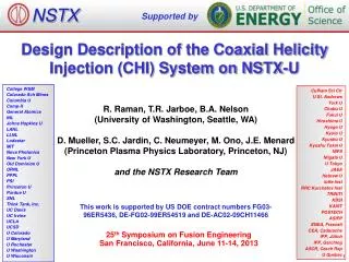
DESIGN, INSTALLATION AND PERFORMANCE OF THE NEW INSULATOR FOR NSTX CHI EXPERIMENTS D. Muellera, M.G. Bella, J. Chrzanowskia, D. Gatesa, J. Menarda, R. Ramanb, T.R. Jarboeb, B.A. Nelsonb, and M.J. Schafferc aPrinceton Plasma Physics Laboratory, Princeton, NJ bUniv. of Washington, Seattle, WA cGeneral Atomics, San Diego, CA Presented at the 21st IEEE/NPSS Symposium on Fusion Engineering 2005 (SOFE05) Knoxville, Tennessee, September 26-29,
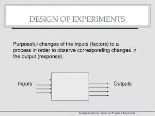
Abstract Coaxial Helicity Injection (CHI), a non-inductive method to initiate plasma and generate toroidal plasma current, is being investigated in the National Spherical Torus Experiment (NSTX). The center stack and outer vacuum vessel are separated by insulating gaps at the top and bottom of the slim central column so that a high voltage (up to 2 kV) can be applied between them from a pulsed power supply or a capacitor bank to initiate an arc discharge. In the presence of a suitable poloidal magnetic field, the discharge is initiated at the lower gap (the injector gap) and because of the strong toroidal field develops a helical structure resulting in substantial toroidal plasma current being driven. In NSTX, up to 390 kA of toroidal current has been generated for an injected current of 25 kA. The early investigations of CHI however frequently developed arcs across the insulator at the top of the machine (the absorber gap) which terminated the desired discharge. This arcing greatly restricted the operational space available for CHI studies. During 2002, the absorber region was modified to suppress these arcs. The new design includes a new ceramic insulator on the high field side of the absorber region with a much longer tracking distance between conducting elements at the different potentials. Furthermore, two new coils were installed near the absorber to minimize the poloidal field connecting the center stack and outer vacuum vessel. During subsequent experimental campaigns, CHI operation was less prone to arcing in the absorber and those arcs that did occur did not terminate the main discharge. 1Work supported by US. DOE Contract No. DE-AC0276CH03073. DM SOFE05 poster
NSTX Is Designed to Explore LowAspect-Ratio Toroidal Confinement Parameters Major Radius Minor Radius Elongation2.5 Triangularity 0.8 Plasma Current 1.5 MA Toroidal Field≤0.6T Heating and Current Drive Induction 0.6Vs NBI (100keV) 7 MW HHFW (30MHz) 6 MW CHI 0.4MA Pulse Length 1 s }A ≥ 1.27 DM SOFE05 poster
Investigating Coaxial Helicity Injection (CHI) for Initiating Toroidal Plasma Current • Inner, outer lower divertors act as electrodes to inject helicity • Magnetic reconnection can convert open to closed flux DC Voltage R. Raman, R. Maqueda DM SOFE05 poster
Obtained 390 kA Toroidal Current for Injector Current of 28 kA • Array of soft x-ray detector sensitive to E > 100eV detect emission from inboard midplane region R. Raman, D. Stutman DM SOFE05 poster
Reason for the change in the absorber insulator design • With the old insulator design, arcs across the gap at the top of the machine occurred frequently (about 2/3 of the shots) on CHI shots (Absorber Arcs) - ExB during CHI drives plasma toward the absorber - A stable, low inductance arc formed that terminated the desired discharge - While a regime that minimized absorber arcs was found, the exploration of other scenarios was problematic • In addition to arcs inside the vessel, arcs in power cables external to the vessel have occurred • Both absorber and external arcs can cause damage DM SOFE05 poster
Absorber arcs terminate discharge • Signature of arc includes an increase in ICHI and reduced noise in VCHI • The discharge transfers to the absorber, Ip goes to zero DM SOFE05 poster
Absorber arcs terminate CHI discharge DM SOFE05 poster
Old Absorber Region Design • Insulator on low field side • Inner and outer vessel can be connected along radial or vertical lines DM SOFE05 poster
New Absorber Design • Insulator on high field side • No simple connection path in insulator region • Coils provide potential to reduce stray field from plasma and PF coils • Flux loops to measure field in absorber region DM SOFE05 poster
Ceramic Installation • Alumina Ceramic • 1.0m (39.37”) OD , 0.91m (35.87”) ID • 25.15 cm (9.9”) total height • 6.35 cm (2.5”) between vacuum surfaces Split ceramic skirt to cover metallic surface DM SOFE05 poster
With new design absorber arcs do not terminate discharge • When arc occurs, main discharge and Ip continue until the CHI voltage is reduced to zero. DM SOFE05 poster
New design, no visible light during the arc and the disharge is not terminated During the discharge before an arc. During arc, main discharge continues and no obvious arc occurs in absorber region DM SOFE05 poster
With no plasma, the CHI coils can reduce the flux and field in the absorber region • Field contours for shot 106488, no Ip, no CHI coil currents • Flux in gap is -7 to -24 mWb • 1000A in inner and 0A in outer CHI coils • Flux in gap is -7 to +10 mWb DM SOFE05 poster
Plasma current reduces the flux and field, but the CHI coils can further reduce them • Field contours for shot 106488, Ip=400 kA, no CHI coil currents • Flux in gap is ~ 4 mWb • 200A in inner and -300A in outer CHI coils • Flux in gap is ~ 1 mWb DM SOFE05 poster
PROBLEM Up to 2 kV supply Hi-pot to 7 kV without MOVs and OH coil Highly variable plasma load Voltage arrestors connecting inner and outer VV through MOVs located ~ 20 feet away Voltage spikes > 3 kV MODIFICATION Move MOVs closer to machine, used 18 inches of coax cable 4 MOV assemblies Reduced inductance of voltage limiting circuit (0.04 H) Arcs external to vacuum Bottom of NSTX No external arcs since modification DM SOFE05 poster
Photo of installed MOV assembly • One of the 4 MOV assemblies • Each assembly has 30 modules mounted between the inner and outer vacuum vessel • 6 modules are mounted between the outer vacuum vessel and building steel • Begin conducting at 1.45 kV DM SOFE05 poster
Significant Improvements to CHI system • Frequency of low inductance absorber arcs that terminate the main discharge has been dramatically reduced • Redesigned absorber region with large new insulator on the high-field side • Relocation of MOVs in the voltage surge protection system reduced inductance which should reduce size of voltage spikes • Installed new flux loops in the absorber region • New coils provide capability to reduce the poloidal field in the absorber region DM SOFE05 poster