Download
1 / 22
220 likes | 221 Views
Discover the ValidWind concept, a small balloon tracer with advanced techniques and results for ground-based remote sensing of wind profiles. Explore its applications, intrinsic accuracy, aerodynamics, data processing, and validation campaigns.

E N D
ValidWind™: Improved Techniques and Results for Ground-Based Remote Sensing of Low Altitude Wind Profiles Working Group on Space-Based Lidar Winds Destin, Florida February 3, 2010 Tom Apedaile Bill Bradford Alan Marchant Danny Scholes Tom Wilkerson ™ USU Research Foundation, 2009
The ValidWind Concept • small balloon tracer • 11” He-filled latex • retroreflector tape • laser rangefinder • built-in inclinometer • integrated compass • bluetooth data link • 3D balloon trajectory • trajectory analysis S/W • ValidWind capabilities: • horizontal range 2km • altitude range 1km • velocity accuracy 1% at all wind speeds • direction accuracy 1º for v > 1m/s • profile resolution 20m • profiling rate 5 – 10 min
Presentation Outline • The ValidWind Concept • Applications for Local Wind Profiling • Intrinsic Accuracy and Aerodynamics • Data Processing • Validation Campaigns • System Improvements
Wind Turbine Micrositing • proposed wind turbine site at the mouth of Logan canyon • supplementary power for USU campus • exploit canyon drainage wind • campaign results: • nocturnal jet develops from the bottom up, then decays coherently • ideal turbine height ~ 100m (unobtrusive) • jet duration 11 hours (winter evaluation needed) Aug 19 Aug 20 time of day (MDT)
Terrain-Induced Wind Field Clarkston ridge, West of Logan 9/19/09 wind vector field constructed from multiple balloon trajectories v > 7 m/s v < 7 m/s altitude w.r.t. sensor (m) leeward terrain horizontal distance (m) NE • wind field cross-section projected to plane 52 from North (the prevailing wind direction on 9/19/09) • strong updraft at the ridgeline transitions to a strong leeward downdraft • horizontal velocity steady at 7.8 ± 1.3 m/s • vertical flow shifts dramatically from +1.6 to -3.5 m/s • preferred turbine location may be slightly leeward
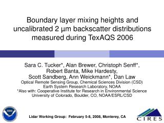
Air Quality Campaign Danish Flats campaign. Air-quality campaign at Danish Flats treatment facility, 10/22-26/09 • ValidWind used to monitor wind profiles. • Wind data coordinated with other instruments to assess fluxes. • Wind data Balloon flights coordinated to provide profiles over the facility. • Good agreement with a 15m tower. • Comparison w/ Remtech sodar. • average speed and direction ok • sodar yields poor profile accuracy ValidWind profiling was performed over or near the processing facility.
History of Balloon Tracers • PIBAL – Pilot Balloon • First described ~1872. • Developed to check upper level winds before manned balloon flights. • Passive balloon. • Direction measured by theodolite. • Range based on a typical rate of ascent. All of these balloons have limited advection accuracy. • Rawinsonde • Weather balloon with telemetry. • Trajectory traced by GPS. • Flights may last hours and extend above the troposphere. • Jimsphere • Metalized balloon, tracked by radar. • Intentionally roughened to minimize “lift instabilities.” • “Standard for upper level wind measurement.”
ValidWind Intrinsic Accuracy • Balloon motion relative to the wind. • CD, Re, terminal velocity • Lift-induced perturbations. • Transient slip.
Aerodynamics of a Sphere • Aerodynamic properties scale with Reynolds number: • where U = velocity (rate of rise) and D = diameter. • For ValidWind, D 13”, Vz ~ 2 m/s, Re ~ 44,000. • For weather balloons, D 2m, Vz ~ 7 m/s, Re ~ 900,000. • The drag coefficient is a function of Re defined by: transition from laminar to turbulent boundary layer subcritical flow CD = 0.4 – 0.5 for all Re of interest supercritical flow
Balloon Terminal Velocity Terminal rate of rise is reached when the drag force cancels the loft: or For the nominal ValidWind parameters, Vz = 2.0 m/s. Observation: trajectory-averaged rate of rise • Loss of He reduces the loft and the expected Vz. (Latex is leaky.) • Up/down drafts contribute variability. • The results are consistent with the spherical balloon model.
Lift-Induced Perturbations “Lift” is an aerodynamic force normal to motion through the fluid. The lift coefficient is analogous to the drag coefficient: Experiments and simulation show CL fluctuating with an amplitude 0.05 – 0.1 for subcritical flow. Fluctuations in CD are much smaller. The typical fluctuation frequency is with a Strouhal number S ~ 0.1 – 0.2. For ValidWind, the fluctuation frequency is 0.5 – 1 Hz. Trajectory perturbations are estimated by integrating the equation of motion: where m’ is the balloon inertial mass plus the aerodynamic “added mass.” For ValidWind, with worst-case values of CL and S, the rms velocity perturbation is sV < 0.2 m/s. This is strongly damped by trajectory averaging. For super-critical flow, CL is somewhat larger. More importantly, CL develops significant power at low frequencies.
Transient Slip • How does the balloon respond to a large velocity offset? • DV with respect to the vertical terminal velocity • balloon launched, starting from rest • balloon passes through an abrupt sheer layer • Equation of motion: • ignoring perturbations due to lift and turbulence • co-moving coordinate system • Solution for transverse motion: • where q atan(V/Vz) and • Transient decay is approximately exponential with a time constant of order 1s. • For DV = 2 m/s, total slip is < 1m. It’s very hard to throw a balloon.
Data Processing - Flow compass inclinometer rangefinder timetag flight reset • Raw Data collected by MatLab script pre-flight trial dust • Parse Data remove false readings • . . . e.g. rangefinder failures, background or foreground interference, telemetry errors. East North AGL Dt • Convert Data to Cartesian coordinates • accommodate asynchronous trajectory sampling • low-pass temporal filter with a uniform scale • smooth the trajectory and estimate velocity in a single step (minimize processing noise) • accommodate wind shear • Filter Data w.r.t. time & Fit Velocity Vector
GQLF Trajectory Filter • Gaussian-weighted Quadratic Least squares Filter. • A type of LOESS (locally estimated scatterplot smoothing) filter. • MatLab m-file: gqlf(t, ti, X, sigma) • {X} are measurements of a cartesian coordinate corresponding to {t}. • {ti} are the evaluation times, bounded by {t}. • The weighting function is exp(-Dt2/2sigma2). s = 10s, typical • Returns NaN if data density is too low (less than 3 data points within ti±3s). • Return values: • qF.b0 profile estimate (at each value ti) balloon trajectory • qF.b1 slope estimate (dX/dt) velocity profile • qF.b2 2nd derivative estimate (d2X/dt2) ~ wind shear vz • qF.errweighted fit error (indicates pointwise quality of b0) • Inputs need not be uniformly spaced. • Filter resolution is uniform all along the trajectory. • For ValidWind vector profiles, repeat GQLF for x, y, and z.
Filtered Trajectory Danish Flats 10/26/09, 10:39 am MDT GQLF filter with s = 10s insufficient sample rate altitude (m, AGL) North East
Residual Errors Flight #1, 10/26/09, Danish Flats • residual errors typically 1 - 2m, consistent with sensor precision and pointing repeatability • errors due to pointing increase with range (r x dq) • velocity uncertainty from a 2m residual is < 0.1m/s
Validation Campaigns Boulder Atmospheric Observatory 300m met tower Sept 30, 2009 (Dan Wolfe, NOAA) miniMOPA Doppler Lidar Sept 29, 2009 (Alan Brewer et al., NOAA)
BAO Comparisons wind speed (m/s) ValidWind vs. BAO: -0.25s ± 1.4s ValidWind results at 100m vs. BAO anemometer at 100m time (hours, MDT) similar resulst at 50, 150, & 200m wind source direction (deg) ValidWind vs. BAO: 28º ± 1.0s • wind velocities are consistent • wind direction offset calibrate ValidWind compass
miniMOPA Comparison • excellent qualitative agreement • wind directions • wind shift event at 23:00 UTC • wind profile features • arrows show wind direction; colors show wind speed
miniMOPA - Agreement • quantitative agreement in the early afternoon and evening • wind velocities • profile features • lidar shows a homogeneous, area-wide wind field
miniMOPA - Disagreement map of Doppler residuals over the ValidWind site • Agreement fails when: • wind shift event at 23:00 UTC • lidar shows strong wind field inhomogeneity • mMOPA verifies a local Easterly wind component
ValidWind Enhancements compass tracking camera rangefinder motorized gimbal • Automatic balloon tracking • increased tracking accuracy • increased sample frequency • eliminate human limitations on balloon tracking • Real-time data processing. • manage the video tracker • automatic data parsing • field displays of trajectories and wind profiles