Download
1 / 29
290 likes | 299 Views
GroundWinds Balloon LIDAR Working Group. M. Dehring, J. Pavlich, C. Nardell, P. Hays , Michigan Aerospace Corp. I. Dors, B. Moore, J. Ryan , University of New Hampshire D. Dykeman, J. Wang, S. Silverman , Raytheon Santa Barbara Remote Sensing. Discussion Outline.

E N D
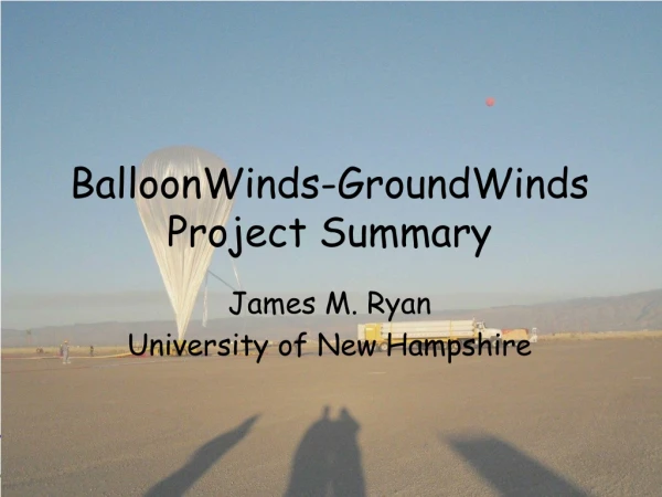
GroundWinds Balloon LIDAR Working Group M. Dehring, J. Pavlich, C. Nardell, P. Hays, Michigan Aerospace Corp. I. Dors, B. Moore, J. Ryan, University of New Hampshire D. Dykeman, J. Wang, S. Silverman, Raytheon Santa Barbara Remote Sensing
Discussion Outline • Mission Overview and Objectives • Interferometer Advancements • Engineering Challenges • Instrument Specifications • Performance Predictions • Summary
BalloonWinds Objective • Overall • Perform a low-cost scientific mission that simulates and validates the fringe imaging wind measurement concept from downward looking high altitude platform • System and Instrument • Fit and function should be similar to a space instrument • Quantify the photometric efficiency of the fringe imaging system • Verify wind measurement capability • Verify parametric LIDAR models
GroundWinds Balloon Concept • Build a balloon payload that • Uses the basic GroundWinds HI and 2nd Generation NH interferometer design • Is optically equivalent to a space instrument • Uses a flash pumped Nd:YAG laser • Uses a ½ m telescope • Uses a streaking CCD approach • Simulates autonomous, satellite-like operation, with on-board data processing • Does not attempt to solve the problems of hardening components, such as the laser, computer, and high-voltage components for use in a vacuum, but does address thermal engineering and test issues
Gondola for Balloon Mission • Gondola provided by AFRL • AFRL Providing • Balloon, helium, “flight train,” parachute • Launch, tracking, cutdown, recovery • Telemetry (transmitters, receivers) • Commands (transmitter, receiver) • CIP (Consolidated Instrumentation Package) • Environmental Chamber (Thermal/Vac) • “High bay” work area (hoist, LAN/Web access, phone, access to commands and data)
Mission Characteristics and Overview • Flight duration 8 hours • 2 hour Accent and Descent • 6 hours at 30 +/- 5 km; Nighttime • Launch out of Ft. Sumner, NM • Payload weight limit 2875 lb
Wind Accuracy and Ranging Objectives • Data Collection Range • Altitude of Balloon to Ground (~30km – 0 km) • 1 km range bins 30 km to 3km • 0.25 range bins 3 km to ground • Horizontal Wind Accuracy • <3.0 meters/sec over full altitude range at 20 second integration times (10 second on chip)
Improvements in the Interferometer • Etalon Design • Improved thermal stability • CLIO Extender • Removes CLIO from CCD • Reduces thermal load and cooling requirements • CCD Camera Redundancy • Aerosol and Molecular Channel fringe images can be combined onto a single camera
Single Camera Operation with Redundancy • Risk Mitigation • Camera failure no longer means un-useable channel • Camera Back-up Increases probability of success • Offers possibility to reduce heat and electrical load • Software advantages • Reduces data storage by ½ • Simplifies Architecture • Reduces computing overhead, CPU time • Reduces memory requirements • Ensures that both molecular and aerosol fringe images are subjected to the same camera state.
Instrument Specifications Comments • The specifications defined in this presentation are based on the minimum requirements to meet the anticipated wind accuracies for the balloon mission • Specifications have been defined for the following sub-systems and components • Telescope and Receive optics • Molecular and Aerosol Etalons • Laser • Etalon Controllers • Component Optical Transmissions • CCD Camera • Most specifications are based on the GroundWinds HI instrument
Specification Considerations for a 355 nm. Balloon Lidar • Sub-Systems must be able to handle the variations in pressure and temperature from launch through landing • Implications of limited and short duration flight time • Telescope and Interferometer alignment must remain stable as balloon ascends into the atmosphere • Alignment changes once in “orbit” must happen quickly to maximize wind profiling time • Operational camera binning schemes have to be thoroughly tested to minimize down time • Laser pointing and power stability have to be well known • Transmission of every component in the balloon instrument must be as high as possible to have a successful demonstration
Receive Telescope Receive Transfer Optics
Pre-Interferometer Component Transmission Requirements and Specifications Interference Filter Note: The filter will be removable in the balloon instrument.
Interferometer Component Transmission Requirements and Specifications Note: Etalon transmission not included
CCD Specifications • CCD design licensed from Pixel Vision • CCD duplication of Hawaii detectors • Table below lists current HI detector characteristics
Laser Specifications • GWNH laser being re-packaged for balloon mission • Table below based on GWNH laser
Expected Molecular Channel Horizontal Wind Errors for a 30 km Balloon Flight (with Interference Filter) Northern Hemisphere Land (NHL) Model RE=2.4-> RE=1.0-> RE= Recycling Efficiency
Expected Molecular Channel Horizontal Wind Errors for a 30 km Balloon Flight (with Interference Filter) Northern Hemisphere Ocean (NHO) Model RE=2.4 -> RE=1.0 -> RE= Recycling Efficiency
Expected Molecular Channel Horizontal Wind Errors for a 30 km Balloon Flight No Interference Filter with Recycling Efficiency=2.4 NHL -> NHO ->
Balloon Schedule • 2003 • Interferometer Design, Build and Begin Testing (MAC) • Telescope Design (Raytheon) • Control System Design-Build (UNH/MAC) • NH Laser Head and Electronics Re-packaging (Raytheon/MAC) • Thermal Control Design (Raytheon) • Detector Build (UNH) • 2004 • MAC System Testing with Test Telescope (MAC) • CDR • Telescope Build (Raytheon) • Thermal/Vacuum Testing Components (UNH/Raytheon/MAC) • Gondola Systems Integration (UNH/Raytheon/MAC) • Balloon/ GroundWinds NH Side-By-Side Testing and Validation • 2005 • Full System Environmental Testing • Balloon Flight