Download
1 / 29
290 likes | 307 Views
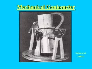
Status of Kappa Goniometer on PROXIMA 1. B. Guimaraes, P. Legrand, P. Gourhant and A. Thompson. Report for Kappa workshop, 28 th - 29 th November 2011. Kappa Gonio of PX1. Large α (50˚), hence large range of crystal orientations. Ω or Φ scans, hence large range of geometries possible.

E N D
Status of Kappa Goniometer on PROXIMA 1 B. Guimaraes, P. Legrand, P. Gourhant and A. Thompson Report for Kappa workshop, 28th - 29th November 2011.
Kappa Gonio of PX1 • Large α (50˚), hence large range of crystal orientations. • Ω or Φ scans, hence large range of geometries possible. • But anti-collision is harder. We use « simple » approach (limit movements) ! • Closer to 20 μ S-O-C than to 1 μ (although < 7 μ part of angular range). In most cases, this has not been a handicap.
News from SOLEIL – PX1 • Goniometer used routinely for 4 years now – collection around ω or Φ with κ non zero (≈ 10%), « normal » collection (≈ 90%). • 5 user groups request, at proposal, « oriented » data collection (large cell, anisotropic diffraction, difficult phasing from « big » object. They are « autonomous »…. • « Most » users have used κ non zero (help from local contact - exceptions « industrials ») • Major upgrade to beamline in July – now have PILATUS detector and shutterless data collection. • Hence gonio motor control / data collect soft changed from « proprietary » (Rigaku) to « in house ». • Additional anti collision hardware added.
Mechanical Integration of Pilatus 6M on PROXIMA 1 – S. LeCouster. • Mechanical design : • Integration of the detector into the existing experimental environment: • Modification of existing detector support with minimal changes • Requirements for translating / offsetting the detector and their impact of design • Counter weighting scheme to avoid vibration / oscillation during detector movements • Protection of the active detector surface (Guillotine): • Positional and translational constraints, limited weight supported by detector, • detector sensitive to vibration • Double function of protection and support for X ray imaging caméra (beam alignment) • I 45° degree X-ray images: • Based on in-house design (detector group) with higher magnification, • stabile support and mounting on guillotine • Beamstop integrated in detecteur • Space limited by guillotine – proximity to detector surface, motorised alignment • Detector connection: • Movable cable tray for coolant and connection to detector needs to permit > 1.25 m of • translation • 3D models to avoid collisions: - • Goniometre/Guillotine • Lighting/Guillotine • Robot/Detecteur
Electronic around the Experimental station • New motion control for Goniometer • Specific trigger system which manages all possibilities of the PILATUS mode • New anti-collision system to secure Pilatus from Goniometer movements New motion control ControlBox DriverBox ServoBox Experimental station PLC Goniometer Pilatus Anti-Collision System SPIBoard Specific Trigger System
Trigger PILATUS • Using a SPIETBOX to trig the Pilatus allow us to select easily trigger modes : • - External Trigger depending on Time • - External Trigger depending on goniometer position • - External Enable adjustable in time • - External Enable depending on goniometer position • All parameters needed to trig the Pilatus are transmitted from tango device to the SPIETBOX through the SPICONTROLLER board. • Two other SPIETBOX are used to duplicate encoders signals and so isolated the motion control from the Pilatus trigger control.
New motion control: ServoBox • ServoBox • New standard power unit for servo motor at SOLEIL (direct current and brushless motor). • ServoBox contains : • Standardized connectors • Power supply: 24VDC (logic) et 48VDC (1KW to motor) • Fans and back plane board • 4 slots for 4 power board (see below) • Directly compatible with ControlBox • Preliminary study and specification written by Soleil • Power board SDB10 • based on an Elmo Whistle OEM component • Numeric amplifier for DC or brushless motor • Rated output current: 10A (Voltage 48V) • Feed back by resolver or incremental encoder • Signals managed: limit switch, thermal sensor, brake • Entire design by Soleil (electronics and mechanics)
Anti-collision • The Anti-collision system is made using position sensors of the three concerned motors. • Each sensor is connected to a PLC. The anti-collision equations is embedded in the PLC which determines if motors must be stop or not. • When specific conditions occurred (see table below), the PLC send to the ControlBox the order to stop the motors and the conditions that activated the security. • Until the operator do an action to unlock motion, all motors are disabled. • After an acknowledge, the ControlBox allow movement only on the direction that will correct the default. • When we are far from the collision area, movements are allowed in both directions. • Still in progress …
PROXIMA1 data collect with Pilatus detector MXCube PX1 Collect Manager PX1 Logging Manager SPIETBox Process & shutter control encoder positions, shutter & detector states, triggers to detector logging Experimental data Filer Meta data Filer Goniometer axis control Beam intensity & X,Y positions logging Detector control ramdisk XBPM control SAC - 24 novembre 2011 - L.Roussier & P.Gourhant
TANGO devices PX1CollectManager & PX1LoggingManager written in Pythonby L.Roussier & P.Gourhant Enabledeasytesting « off line » (hardware + motor test bench ) quick and easy adaptation for beamlinerequirements & MXCubeinterfacing Shutterless (continuous) collect Hardware synchronisation between axis position and shutteropening /closing 4 Pilatus trigger modes implemented(external trigger or gates) Mode currentlyused (via SPIETBox) : open the shutter, give an external trigger for the first image count acquired images from the detector, close the shutterwhen all are acquired Experimental data directlysaved on ramdisk by the detector software PX1CollectManager starts the meta-data logging, whichworks full independently(the collectisn'tdisturbed if the loggingdoesn'twork) Process control implementation SAC - 24 novembre 2011 - L.Roussier & P.Gourhant
Meta data logging along the collect Objectives : - Collect system characterization and improvements in terms of synchronization, reproducibility, axis velocity. - Preventive degradation of equipment. - Future correlation with diffraction images Implementation : - Flyscan mechanism - Frequency : 1 kHz - In parallel : Periodic beamline sensors archiving First results of analysis (Python scripts) - Parameters optimisation of the collect ( Delay before first image for constant speed) - Omega behaviour better than Phi (speed regularity,…) SAC - 24 novembre 2011 - L.Roussier & P.Gourhant
Meta data first analysis Collect axis : Omega Have improved PID, acceleration time for omega – phi axis is much worse by comparison : we have not yet got the same level of control / following error as the Rigaku hardware achieved. Data quality is good, but not quite as good as using omega – improvements needed. SAC - 24 novembre 2011 - L.Roussier & P.Gourhant
ADSC 315r Max 3 images/sec. Fastest on PX1 is 12 images/min. Binary images of 18 Mb. Up to 180 Gb per day (uncompressed). PILATUS 6M Maximum speed of 12 images/s "cbf" format (binary 32bit compressed imagesCIF) 6-7Mb/image. Collect of 3Gb in 1 or 2 min in continuous mode (85 Mb/sec), every 5 to 10 min – gives max of 800 Gb per day. We typically collect 400 – 500 Gb per day (compressed).
PROXIMA 1 – R. Barbosa, P. Gourhant, B. Guimaraes, P. Legrand, F. Blache and S. Pierre-Joseph PROXIMA 2 – W. Shepard, D. Duran, G. Fox, T. Moreno, A. Buteau Staff directly involved on PX1 – PX2. Collaborations – Global Phasing, Insititut Pasteur (F. Rey), CNRS – Marseille (S. Spinelli), CNRS Gif sur Yvette (S. Fieulane)
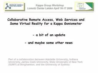
BioSTRUCT-X – What we proposed Sept 2011 – Sept 2015. • 2 Workshops for Scientific / Technical Development. • 2 User training courses (crystallography?) • Accessibility at each SR site • Validation
Validation • High α vs low α. Do we have enough knowledge to advise people? • Do our measured performances mean the same things? What are the best characterisation methods? • Precision of alignment methods and impact on experiments? • What protocols are we sure of, and how do we choose between them (automatic) / when do we ask for user input.
Actions / Discussion. • Whodoes not want to participate (no funding for non EU of course)? • Review of availablebeamlinefacilities – underway : I willcirculate a version around Christmas for you to verify and complete. • Plan for first full meeting. Subject, when (beforeOct 2012) and where. • Think about validation (not comparative) criteria (technical and crystallographic) / measurementmethods.
What we need to do better at SOLEIL • Anti-collision. In some orientations can use κ of 90˚, but we don’t to make collisions impossible. • Radius of S-O-C. Can get the gonio to work fine (≈7 μm) but only in hemisphere « towards source ». The moment ω « goes over to the dark side », centre jumps 20 μm! Solution is to repair it, but we also need to better characterise (automatically?). • Between first two, only us 25% of capability of our gonio. • Properly understand the best way to use the goniometer, to advise users correctly. • Train the 90% of users that are « not autonomous »!
Difficult structure solution - 1. • Contacted SOLEIL with inhouse data he couldn’t index. • Came with unfrozen crystals. • Collected native data 1.9 Ǻ resolution, with a maximum cell edge of 500 Ǻ . • Gd derivative obtained on site – structure solved by SAD (in refinement).
Difficult structure solution - 2 • Problem was to get phases (quickly!) as MR solution incomplete. • Tricky data collection because of diffraction “spot shape” (Ho derivative). • Os derivatives – site had high B factor and gave phases to low resolution. κ geometry critical. • Collaboration with I.P and Global Phasing.