Download
1 / 11
120 likes | 133 Views
Schematics 201 Lecture Topic: Electrical Symbols. 02-23-2011 . Agenda for the week. Test # 1. Discuss Electrical Symbols Start Assignment # 6. FM Tuner Schematic. Graphic Symbols. The symbols are shown in and page 930 of the Engineering Book.

E N D
Agenda for the week • Test # 1. • Discuss Electrical Symbols • Start Assignment # 6. FM Tuner Schematic.
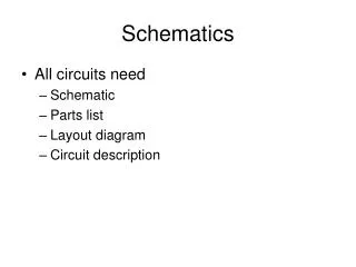
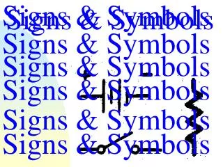
Graphic Symbols • The symbols are shown in and page 930 of the Engineering Book. • The size and line thickness do not affect the meaning of the symbol. The symbols should be drawn to a proportional size based on the space needed.
Graphic Symbols in Problem 26-.42 • Diodes - A diode is an electrical device allowing current to move through it in one direction
Graphic Symbols in Problem 26-.42 • Capacitor - A capacitor stores electric charge. A capacitor is used with a resistor in a timing circuit. It can also be used as a filter, to block DC signals but pass AC signals. • Capacitors are widely used in electronic circuits to block the flow of direct current while allowing alternating current to pass, to filter out interference, to smooth the output of power supplies, and for many other purposes. They are used in resonant circuits in radio frequency equipment to select particular frequencies from a signal with many frequencies.
Graphic Symbols in Problem 26-.42 • An amplifier is an electronic device that increases the voltage, current, or power of a signal. Amplifiers are used in wireless communications and broadcasting, and in audio equipment of all kinds. They can be categorized as either weak-signal amplifiers or power amplifiers. Weak-signal amplifiers are used primarily in wireless receivers. They are also employed in acoustic pickups, audio tape players, and compact disc players. A weak-signal amplifier is designed to deal with exceedingly small input signals, in some cases measuring only a few nanovolts (units of 10-9 volt). Such amplifiers must generate minimal internal noise while increasing the signal voltage by a large factor. The most effective device for this application is the field-effect transistor. The specification that denotes the effectiveness of a weak-signal amplifier is sensitivity, defined as the number of microvolts (units of 10-6 volt) of signal input that produce a certain ratio of signal output to noise output (usually 10 to 1). • Power amplifiers are used in wireless transmitters, broadcast transmitters, and hi-fi audio equipment. The most frequently-used device for power amplification is the bipolar transistor. However, vacuum tubes, once considered obsolete, are becoming increasingly popular, especially among musicians. Many professional musicians believe that the vacuum tube (known as a "valve" in England) provides superior fidelity.
Graphic Symbols in Problem 26-.42 • Transistor - A transistor amplifies current. It can be used with other components to make an amplifier or switching circuit. • There are two types of standard transistors, NPN and PNP, with different circuit symbols. The letters refer to the layers of semiconductor material used to make the transistor. Most transistors used today are NPN because this is the easiest type to make from silicon.
Graphic Symbols in Problem 26-.42 • A resistor restricts the flow of current, for example to limit the current passing through an LED. A resistor is used with a capacitor in a timing circuit.
Graphic Symbols in Problem 26-.42 • Inductor - A coil of wire which creates a magnetic field when current passes through it. It may have an iron core inside the coil. It can be used as a transducer converting electrical energy to mechanical energy by pulling on something.
Assignment #6 • Start assignment by making use of blocks and dynamic blocks for each symbol with the symbol description. Read and follow instructions.