Download

1 / 30
440 likes | 1.24k Views
Reading Electrical Schematics. Lesson Objectives. Understand various schematic types. Trace through sequence of operation using ladder diagrams: Heating, cooling and defrost cycles. Introduction. One of the largest single influences on our daily lives is electricity.

E N D
Lesson Objectives • Understand various schematic types. • Trace through sequence of operation using ladder diagrams: • Heating, cooling and defrost cycles.
Introduction • One of the largest single influences on our daily lives is electricity. • Electricity affects each of us in hundreds of ways every day. • All heating and cooling equipment utilizes electricity. • Technicians must understand the principles of electricity. • One of the most important skills that you must have is the ability to read electrical schematics.
Electrical Schematics • Electricity is a large part of the HVACR technicians job. • Electrical schematics provide a road map through the electrical systems: • Sequence of operation. • Location of components. • Function of components. Every HVACR manufacturer provides drawings of the electric circuits in its equipment. These drawings describe the sequence of operation, and indicate the location and function of key electrical components in the system. Think of a wiring diagram as a road map of an electric circuit. Once you understand how these drawings are constructed, you will have a clearer picture of the information they convey. By studying the schematics provided with the equipment, you will be able to discern intended sequences of operation. Armed with this information, you can more quickly troubleshoot an electrical problem and systematically locate any fault.
Wiring Diagram Types • Pictorial. • Point-to-point. • Ladder. • Many manufacturers will use some combination of the three. There are three basic types of wiring diagrams that you must be able to read effectively—pictorial diagrams (sometimes called “component arrangement” diagrams), point-to-point diagrams, and ladder schematics. Some drawings include both pictorial diagrams and ladder schematics. The international wiring diagram style also has become common in the HVACR industry.
Fundamental Principles In all cases, some fundamental principles can be applied to the reading process. Whenever you are reading a drawing that illustrates electric circuits, keep the following basic points in mind: • Electricity always follows the path of least resistance. • An electric circuit must have a power source. • An electric circuit must have a load (some device that consumes electric power). • An electric circuit must have a path from the power source to the load and back to the power source.
Fundamental Principles • There is almost always only one load per circuit. • There is almost always only one control switch per load. • When used, safety switches must be connected in series to protect the load. • Electrical schematics are shown with the circuits de-energized, unless otherwise stated.
Fundamental Principles • Electricity follows the path of least resistance. • A circuit must have a power source, load and path. • 1 Load per circuit (parallel). • In most cases – one switch per load. • Safety switches connect in series. • Schematics are shown de-energized. Regardless of the type of diagram, these basic principles apply. If any of the requirements above are not met, the circuit is incomplete and function will suffer. Take a moment to note bullets 3 and 4 in the list above. Loads are rarely connected in series because they would have to share the electric power. You may occasionally encounter resistive heaters connected in series—the practice is rare, however, and keep in mind that the system designer does so to achieve some specific purpose. Motors must never be connected in series, since they cannot “share” a power source and operate successfully. You will almost always find only one control switch for each load. In some cases, you may find more than one control switch capable of operating a load. For example, both the thermostat and the defrost control are capable of operating the supplemental heat in the electric furnace used with a heat pump.
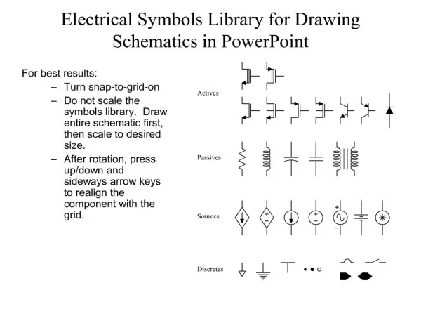
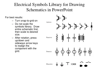
Symbols • The components used to build an electric circuit are represented in wiring diagrams with symbols. Depending on the manufacturer, different symbols are sometimes used to depict the same component. This is unfortunate, but the variety of symbols in use should not limit your ability to read and interpret electrical drawings successfully. • Power-passing devices: • Switches. • Wires. • Power-consuming devices – Loads: • Inductive – motors and coils. • Resistive – heaters. • Circuit boards (terminals). • See next slide.
Symbols Symbols are used to depict components in a circuit that are either power-passing devices or power-consuming devices. Power-passing devices include switches and wires. They are intended to deliver electric power to loads without using any of the power they are passing through the circuit. Power-consuming devices are loads intended to perform work in exchange for the power they consume. Power-consuming devices used in HVACR equipment are generally inductive loads (such as motors) or resistive loads (such as electric heaters). People often think of “loads” as large power-consuming devices in the line-voltage circuit. Line voltages can range from 120-V single-phase to 460-V three-phase power (or higher). But loads also are present in low-voltage circuits. Power-consuming devices employed in the control circuit are typically magnetic coils or thermal heaters used to open or close switches.
Pictorial Diagram • A pictorial diagram is intended to illustrate the actual locations of various components as they are positioned in a control cabinet. Very often, lines depicting wiring are not drawn on the diagram, since it is not meant to be used as a tool for tracing individual circuits. The pictorial diagram’s function is to assist you in finding a particular circuit component that may need to be tested or replaced. • The figure shown on this slide is an example of a pictorial diagram. It illustrates the arrangement of components in the control box of a basic packaged gas-electric system. As you can see, it is not possible to determine the sequence of operation from this type of drawing. There are no individual wires drawn in to show how the components are connected. To determine the sequence of operation, you would need to view the ladder schematic for this system.
Ladder Schematic • Shows specific paths. • Best for trouble-shooting. • Shows how electricity gets through switches and to loads. A ladder schematic is a drawing intended for tracing specific circuits. Notice that the circuits for individual loads are separated into specific pathways. Each circuit is drawn with switches and loads connected by lines. The lines do not necessarily illustrate the point-to-point connections that may exist in the unit. The ladder schematic economizes by showing how components function together.
Lines • Be aware that in many (but not all) schematic diagrams, the convention used to distinguish factory-installed wiring from field-installed wiring is as follows: • Solid heavy lines indicate factory-installed line-voltage wiring. • Dashed or dotted heavy lines indicate field-installed line-voltage wiring. • Solid light lines indicate factory-installed low-voltage wiring. • Dashed or dotted light lines indicate field-installed low-voltage wiring. • Heavy Solid: • Factory-installed line voltage. • Lighter solid: • Factory-installed control voltage. • Heavy dashed: • Field-installed line voltage. • Light dashed: • Field-installed control voltage.
Reading the Sequence of Operation • Specific circuits will be illustrated on the following pages: • Observe the circuits highlighted in red. For purposes of illustration, let’s isolate specific circuits in our sample gas-electric system and describe the sequence of operation as revealed by a reading of the schematic. Follow along by observing the circuits in the figures that are highlighted in red.
Call for Cooling This illustration shows what happens on a call for cooling. When the 240-V circuit is energized, the transformer is active and supplies 24 V to the control circuit. The completed circuit begins at the secondary side of the transformer. Low voltage is supplied to the “R” terminal on the thermostat subbase. The system switch is closed to the “COOL” mode of operation, which allows low voltage to reach the cooling mercury switch. Since the room temperature is above the thermostat setpoint in this example, the mercury switch is closed. Low voltage is allowed to pass to the “Y” terminal on the subbase. From there, the control voltage has two available paths to follow. It passes to the “FAN” switch, which is closed to the “AUTO” position, and to the “G” terminal on the subbase. From the “Y” terminal on the subbase, low voltage is also directed to the magnetic coil in the compressor contactor. At the same time, control voltage passes from the “G” terminal on the subbase to the magnetic coil in the indoor blower relay. A path to these low-voltage loads from one side of the transformer is now complete. However, a path returning to the power source (the transformer) also must be complete before the loads can be energized. By tracing through the coils, you will find that there are no switches in the return path, so a completed 24-V circuit exists for both low-voltage loads. If there are no faults in any components in the circuits, both magnetic coils are now energized and they will move the switches that they control.
Cooling Cycle The switches that these two magnetic coils control are located in the line-voltage circuit. Look at the figure on the slide. Trace the highlighted circuit in the high-voltage side of the diagram to determine which loads each coil controls. The L1:T1 and L2:T2 contacts in the compressor contactor are closed by its energized magnetic coil, which is supplied with control voltage through the “Y” terminal on the thermostat’s subbase. Both the compressor motor and the outdoor fan motor are being supplied with line voltage through the L1:T1 closed contacts. Observe that no other switches in the circuit are supplying power to both motors. A completed circuit exists from the L1 leg through the closed L1:T1 contacts to and through both motors to the closed T2:L2 contacts, returning to the power source by way of the L2 leg. If no faults exist in the circuit, both motors will be running. Be sure to note a change in the indoor blower relay switches. The switch located between terminals 4 and 2, which is normally open, is now closed because the relay’s magnetic coil is being supplied with control voltage through terminal “G” on the thermostat subbase. The closed switch provides a completed line-voltage path from the L1 leg to and through the indoor blower motor, returning to the power source by way of the L2 leg. If no faults exist in the circuit, the indoor blower motor will be running. Also notice that the normally closed contacts 4:5 of the indoor blower relay are now open. This prevents the circuit from energizing the multispeed indoor blower motor on two different speeds at the same time. Doing so would damage the motor. These three motors will continue to operate until the room temperature drops to the setpoint and the thermostat is satisfied. At that point, the mercury switch in the thermostat will open and de-energize the compressor contactor coil and the indoor blower relay coil. Their associated contacts and switch will return to their normally open positions, thus removing power from the motors, which will stop running. When the room temperature rises above setpoint, the process begins again automatically.
Heating Cycle • Safety switches must be connected in series with the control switch. If they were connected in parallel, all safety switches would have to open at the same time in order to interrupt the circuit and protect the device. Once again, let’s isolate specific circuits for the purposes of illustration. The illustration on this slide shows the safety switches that are being used to protect the heating components in our packaged gas-electric unit. The safety switches include: • No. 1 limit (normally closed temperature switch opens on rise). • No. 2 limit (normally closed temperature switch opens on rise). • Combustion air (normally open pressure switch closes on rise). • Low gas pressure (normally open pressure switch opens on fall). • Notice that these safety switches are connected in series with the thermostat heating switch, which is supplying control voltage through the “W” terminal on the subbase. The system switch must be moved to the “HEAT” mode, and the thermostat’s control switch—together with all of the safety switches—must be closed before control voltage can be supplied to the gas valve solenoid. By referring to the high-voltage side of the diagram, you will see that the combustion air blower runs continuously when line voltage is supplied to the circuit, since there are no control switches in that circuit. When the blower is operating properly, the combustion air-proving switch will close (assuming that there is no problem with the switch). The result of this action is that all of the safety switches are in the closed position. When the system is in the heating mode and the heating switch in the thermostat closes, the gas valve will operate (again assuming that no faults exist elsewhere in the circuit). • By “reading” the schematic, you can see that the two circuits in this system are linked in function. The combustion air blower circuit must be complete and energized (with no faults present) to close the combustion air-proving switch in the string of safety switches located in the control circuit. This demonstrates how a schematic “describes” relationships between components in a system.
Heating cycle Let’s isolate one more circuit in our packaged gas-electric system to further illustrate this point. Look atthe figure on this slide. Notice that whenever the system switch is in the “HEAT” position and the heating switch in the thermostat is calling for heat, the heater in the indoor blower delay relay (IBDR) located in the control circuit is energized. This action, which closes the IBDR contacts M1:M2 in the line-voltage circuit and energizes the indoor blower motor, provides a delayed-time function for bringing on the indoor blower in a heating cycle.
Heating cycle – IBDR circuit The gas burner is now functioning and heating the heat exchanger, which in turn provides the heat needed to close contacts 2:4 of the indoor blower delay relay (IDBR) in the temperature-actuated blower control. At this point, two line-voltage paths are supplying voltage to the indoor blower motor as shown on the slide.
Temperature “OFF” Function When the room temperature has been satisfied, the heating switch in the thermostat will open and de-energize the control circuit to the gas valve solenoid and the IBDR heater. This action opens the gas valve and terminates burner activity. It also opens contacts M1:M2 in the IBDR. The indoor blower motor, however, will continue to run, because the blower control temperature switch contacts 2:4 are still closed. They will remain closed until the indoor blower has sufficiently lowered the temperature of the heat exchanger to prevent stressing the metal, which could shorten the life of the heat exchanger. This action provides a temperature “OFF” function (see the figure on this side). By reading the schematic, you have discerned that the control system uses a timed “ON” and temperature “OFF” strategy for operation of the indoor blower motor during the heating cycle.
Trickle Heat Circuit The ability to read a schematic gives the skilled technician a keen insight into understanding how the manufacturer wants its equipment to operate. For example, by studying the illustration on this slide, you will see that this manufacturer is using the start winding in the compressor to provide crankcase heating during the “OFF” cycle. The use of a contactor that opens only one leg of the 240-V single-phase circuit provides a path for a “trickle circuit” through one of the pair of run capacitors. The figure on this slide shows the path from L1 through the capacitor (C-a) and the start winding, returning to the power source at L2. It is very important for a capacitor (C-a) with the correct capacitance to be used in the trickle circuit. An improperly sized capacitor will damage the start winding in the compressor. In each of the examples above, the schematic indicates that the crankcase heater is on only when the compressor is not operating. Crankcase heat is not needed when the compressor is running. In some systems, however, the crankcase heater is energized whenever voltage is supplied to the outdoor section—even when the compressor is operating. This method of crankcase heat will be covered later.
Dual Run Capacitors The trickle circuit ensures that crankcase heat is provided only when the compressor is off. When the L1:T1 contacts close in the contactor (MS), the two compressor capacitors (C-a and C-b) are connected in parallel. Their capacitance values are added, since each capacitor is being supplied with full line voltage. The capacitance of the start winding is then equal to that of the sum of the two run capacitors. The figure on this slide shows the dual run capacitors in the highlighted circuit. Note another feature of this system relating to the condenser fan motor. The fan motor thermostat (TH) is depicted in this slide as a single-pole, double-throw (SPDT) switch. When the outdoor ambient temperature is high, the thermostat closes to the “HIGH” fan speed. This provides enough air flow to keep the head pressure from getting too high. When the unit is operated in the cooling cycle during mild weather, the fan motor thermostat closes to the “LOW” fan speed. This reduces the air flow through the condenser coil, thus increasing the head pressure enough to maintain a solid column of liquid to the metering device.
Crankcase Heater Circuit Now look at the schematic on this slide. Study it for a moment and see if you can determine when the crankcase heater will be energized. When the L2:T2 contacts in the contactor (MS) are open, the compressor motor is off. The crankcase heater is connected to L2 directly and to L1 indirectly through the run winding of the compressor motor. The resistance value of the run winding is much lower than the resistance value of the crankcase heater, with the result that the run winding serves as a path to the heater. The heater, therefore, is energized and providing heat to the crankcase oil when the contactor coil is de-energized and the L2:T2 contacts are open. The path for this crankcase heater circuit is shown on the next slide.
Energized Crankcase Heat Shown on this slide is the circuit you should have identified. Note that when the contactor contacts L:2 and T:2 are open, the completed circuit to the crankcase heater is through the run winding of the compressor motor and back through the contactor contacts L:1 to T:1.
De-energized Crankcase Heater Electricity always follows the path of least resistance. When the L2:T2 contacts are closed, the current will bypass the crankcase heater, since the switch in the contactor has no resistance (if it is not defective). The crankcase heater, therefore, is de-energized when the contacts are closed and the compressor is running. This function is illustrated on this slide.
Defrost Initiation When the accumulated compressor run time has satisfied the frequency set by the technician, the defrost cam will close the open switch in the timer control for a brief moment. This will supply voltage to the defrost thermostat. If there is insufficient ice accumulation on the outdoor coil to warrant a defrost cycle, the defrost thermostat will remain open and a defrost cycle will not be initiated, as shown in the upper schematic on this slide. If the ice accumulation on the outdoor coil is reducing air flow by 50% or more, the refrigerant line will be sufficiently cold to close the defrost thermostat. This will supply voltage to the defrost relay coil. The normally closed contacts in the defrost relay will open, turning the outdoor fan motor off and decreasing the amount of time required to defrost the outdoor coil. The normally open contacts in the defrost relay will close and supply voltage to the defrost relay coil through the second cam switch in the defrost timer and the defrost thermostat. The reversing valve will switch to operate in the cooling cycle, which will direct high-pressure hot gas into the outdoor coil to supply the heat necessary for defrosting the coil. The defrost relay, when energized, will also bring on the resistance heat to temper the indoor because the system is now in the cooling mode during defrost. In the case of a heat pump installed with a fossil-fuel furnace, the furnace may be cycled on and off to temper the indoor air and to provide additional heat to speed up the defrost cycle. (The low-voltage circuit to the reversing valve solenoid and the supplemental heat is not shown in this schematic.)
Defrost Latching Circuit The first cam switch in the defrost timer is closed for only a very short time. It opens as the defrost timer motor continues to run. The defrost relay coil is supplied with voltage through a latching circuit that has been created through the now-closed switch in the defrost relay. You can follow this operational sequence by reading the schematic on this slide.
Defrost Termination One of two events will terminate the defrost cycle in this control system. The first event relates to the defrost thermostat (see the upper schematic on this slide). When the outdoor coil has been completely defrosted, the refrigerant temperature will rise and the defrost thermostat will open. This interrupts the circuit to the defrost relay coil and terminates the defrost cycle, even if the second cam switch in the defrost timer remains closed. The de-energized coil in the defrost relay causes the relay’s contacts to reverse position, thus bringing on the outdoor fan motor. The reversing valve then switches to the heating cycle, returning high-pressure hot gas to the indoor coil to provide normal heating, and de-energizing any supplemental heat source that energizes during the defrost cycle. (Again, the low-voltage circuit to the reversing valve solenoid and supplemental heat source is not shown in this schematic.) The second event relates to the defrost timer cam switch (see the lower schematic on this slide). When the defrost timer reaches the prescribed termination time limit, the second cam switch will open momentarily and interrupt the circuit to the defrost relay coil, even if the defrost thermostat is closed. The second cam switch will open 10 to 15 minutes after defrost has been initiated, depending on the control being used. This action de-energizes the defrost relay coil and terminates the defrost cycle. The de-energized coil in the defrost relay causes the relay’s contacts to reverse position, thus bringing on the outdoor fan motor. The reversing valve switches to the heating cycle, returning high-pressure hot gas to the indoor coil to provide normal heating.
Lesson Summary • A wiring diagram is a road map of an electric circuit. • 75% of all service calls involve electrical troubleshooting. • The most common types of wiring diagrams are the pictorial diagram and the ladder schematic. • The pictorial diagram shows the general location of electrical components in the control cabinet. • The ladder schematic shows the sequence of operation for the system. • The use of SI diagrams has gained in popularity among many manufacturers of HVACR equipment. • Regardless of the type of wiring diagram used, the rules for reading a schematic remain unchanged. • Practice is important to success as a service technician.