Download
1 / 28
280 likes | 396 Views
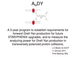
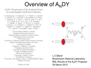
A N DY Trigger and DAQ System. Chris Perkins UC Berkeley/Space Sciences Laboratory Stony Brook University. A N DY Review. 11/08/2011. A N DY Measurement Requirements. Want to measure π 0 and high pair-mass Drell -Yan continuum between J/Ψ and ϒ

E N D
ANDY Trigger and DAQ System Chris Perkins UC Berkeley/Space Sciences Laboratory Stony Brook University ANDY Review 11/08/2011
ANDY Measurement Requirements • Want to measure π0 and high pair-mass Drell-Yan continuum between J/Ψ and ϒ • Need to measure Invariant Mass and Position of reconstructed particles • Need sufficient resolution of deposited energy and position • Beam-Beam Counters (BBC) need relatively crude timing resolution of hits for basic Minimum Bias Trigger • RHIC Crossing Rate : 10 MHz • Hadronic Interaction Cross Section : ~30 mb • Drell-Yan Signal Cross Section : ~7 x 10⁻⁵mb at 500GeV • Need reconfigurable Digital Trigger System/Pattern Recognition to distinguish signal from other interactions Chris Perkins
Portability of Trigger/DAQ System • Overall design of ANDY Trigger/DAQ system was ported from STAR Experiment Trigger System Portion of STAR Trigger Tree ANDY Trigger Tree – Run 2011 • System and custom electronics have general utility as Trigger/DAQ system for other experiments Chris Perkins
Trigger and DAQ System Overview All Custom Designed and Built Electronics Digitization, Buffering, Preliminary Trigger Algorithms DAQ Receiver (Linux) Custom Data Network Start/Stop Data Taking Triggering Chris Perkins
Digitizing, Buffering, and Trigger Algorithm Boards QT Boards : • 32 Analog Input channels • 32 Digital Output bits • To Trigger Tree • 32 Discriminator Outputs • For timing triggers • Programmable FPGA over VME • For Trigger algorithms • Digitizes Analog PMT Input Signals • Buffers incoming data • Performs initial Trigger Algorithm on data • Trigger data Read out over VME • Onboard Memory: Enough to store 7ms worth of data • Low Noise: RMS Pedestal variation < 1 count Chris Perkins
QT Boards (Continued) • Custom designed charge integrator circuit for PMT input signals • 12-bit, 70 MSPS Analog-to-digital converters • Configuration programmable over VME: • Daughterboard FPGAs (containing trigger algorithms) • Digitizer Gate Start/Stop (1 ns steps) • Discriminator Thresholds • Dynamic range and sensitivity: • 0-200 GeV, ~0.05 Gev (12 bit dynamic range) • ~ 0.25 pC/count ADC • Linearity over the full range • Active Capture Time: ~85ns per crossing (~85%) Motherboard Datapath Daughterboard Datapath Chris Perkins
Data Storage and Manipulation (DSM) Boards • 128 Digital Input bits • Differential Signaling • From QT or DSM • 16 channels x 8 bits • 32 Digital Output bits • Programmable FPGA over VME • For Trigger Algorithms • Buffered data readout over VME • Performs trigger algorithm on 128 input bits to produce 32 output bits for next layer of trigger tree DSM Datapath Chris Perkins
Clock Distribution • Need to keep all boards in sync across many VME crates • Custom designed RHIC Clock and Control (RCC) Board • Buffers incoming clock from accelerator (~ 10 MHz) • Fans out clock and control signals to individual trigger boards and digitizer board VME crates • Configurable phase controls Chris Perkins
Data Acquisition Receiver • Individual boards in each VME crate are readout over the VME backplane • Data is sent to an aggregating DAQ receiver over a custom built Fiber Data Network (overall data rate ~ 2 Gb/s) • Standard Linux machine (DAQ) houses custom built PCI card to receive digitized and triggered data • Current bottleneck is boards readout serially over VME backplane • Additional VME crates/Trigger boards can be added to system with no penalty because VME crates readout in parallel • Events can currently be collected at ~ 3kHz depending on detector occupancy • Further optimization is still ongoing • Token indexing system correlates packets from each crate and assembles into full event Chris Perkins
ANDY Experimental SetupRHIC Run 2011 ZDC-Yellow ZDC-Blue BBC-Yellow Chris Perkins
ANDY in January, 2011 Trigger/DAQ electronics Left/right symmetric HCal Left/right symmetric ECal Blue-facing BBC Left/right symmetric preshower Beryllium vacuum pipe Chris Perkins
Trigger Electronics Tree – Run 2011 • Digitizers/Buffering/Data Manipulation • Digital Trigger Tree • Data funnels through digital electronics • tree with algorithms performed at • each level • Last board in tree makes final decision • whether or not to trigger and readout • data • Trigger algorithms in FPGAs for easily • reconfigurable triggers (over VME) • Trigger system can look at every RHIC • crossing for a trigger (10 MHz) • (nearly zero deadtime) Chris Perkins
Trigger Crate Layout – Run 2011 • 3 Total VME Crates Chris Perkins
Detector Diagram – Run 2012 • Add 20 HCAL Modules to close gap above and below beam pipe • Test GEM Trackers using independent Scalable Readout System (SRS) Chris Perkins
Trigger Electronics Tree – Run 2012 • Add 20 HCAL Modules • Signals will fit into existing HCAL QT Boards • No Changes to Trigger Tree from Run 2011 Chris Perkins
Trigger Crate Layout – Run 2012 • Same as Run 2011 Chris Perkins
Detector Diagram – Run 2013 • No BBC Blue • Add new PreShower • Add ECal Blue • Old PreShower -> Mid Y • ECal -> Ecal Yellow • Expanded HCAL • Add first two GEM tracking stations (not shown) • Triggered from trigger system • Readout using “Scalable Readout System” (SRS) • Data Acquisition independent from rest of AnDY DAQ system Chris Perkins
Trigger Electronics Tree – Run 2013 • No BBC Blue • (-1 QT) • Add new PreShower • (+10 QT) • Add ECal Blue • (+50 QT, +9 DSM) • Old PreShower -> Mid Y • ECal -> Ecal Y • Expanded HCAL • (+2 QT) Chris Perkins
Trigger Crate Layout – Run 2013 • 10 Total VME Crates will fit into existing STP Data Network • Crates readout in parallel so same DAQ rate capabilities Chris Perkins
Detector Diagram – Run 2014 • Add Third Tracking Station Chris Perkins
Trigger Electronics Tree – Run 2014 • Add Third Tracking station • Detector Implementation still TBD as well as Trigger/DAQ Interface • Trigger Tree same as Run 2013 until Tracking finalized Chris Perkins
Trigger Crate Layout – Run 2014 • Same as Run 2013 until Tracking design is finalized Chris Perkins
Reconfigurable FPGA Trigger Algorithms • The following triggers have been developed so far and can be interleaved with each other during data-taking: • LED (for monitoring detector stability/gains) • Cosmic-rays (for relative calibration of Hcal) • Minimum-bias (based on BBC) • ECal Sum (for triggering on π0) • HCal Sum (for triggering on jets) • ZDC (for local polarimetry) Chris Perkins
Jet Trigger • Jet Trigger = Threshold on HCal Sum with BBC collisionrequirement • Crossings before and after Jet trigger are relatively clean • Delivered luminosity is fully recorded, with minimal impact from livetime Chris Perkins
Example : Jet Triggered Events • Select from jet-trigger events for HCal “high-tower” to be centered in module • Display for each detector of each module the ADC count as color scale (black=greatest count yellow=lowest count) • Events look “jetty”, as expected Chris Perkins
Scaler Boards • Capable of capturing input bits for every RHIC crossing (~10 MHz) • Currently 30 input bits but easily expandable in the future • Data is streamed to Linux Data Receivers and stored on disk Top Bottom Chris Perkins
Conclusions • STAR Trigger System Infrastructure Design was successfully ported to AnDY Trigger/DAQ System for Run 2011 • A suite of simultaneously running triggers was developed and used in 2011 • Expanded detector set in future runs will fit into current Trigger/DAQ system while retaining current DAQ rate capabilities Chris Perkins
Backup Slides Chris Perkins