Download
1 / 51
510 likes | 646 Views
A N DY. E.C.Aschenauer, A. Bazilevsky, L.C. Bland, K. Drees, C. Folz, Y. Makdisi, A. Ogawa, P. Pile, T.G. Throwe Brookhaven National Laboratory H.J. Crawford, J.M. Engelage, E.G. Judd University of. California, Berkeley/Space Sciences Laboratory C.W. Perkins

E N D
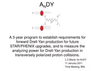
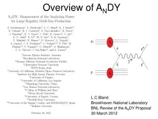
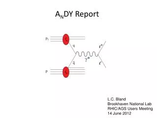
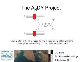
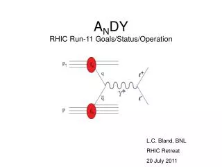
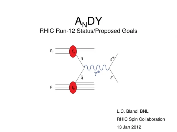
ANDY E.C.Aschenauer, A. Bazilevsky, L.C. Bland, K. Drees, C. Folz, Y. Makdisi, A. Ogawa, P. Pile, T.G. Throwe Brookhaven National Laboratory H.J. Crawford, J.M. Engelage, E.G. Judd University of. California, Berkeley/Space Sciences Laboratory C.W. Perkins University of. California, Berkeley/Space Sciences Laboratory /Stony Brook University A. Derevshchikov, N. Minaev, D. Morozov, L.V. Nogach Institute for High Energy Physics, Protvino G. Igo University of California, Los Angeles M. Grosse Perdekamp University of Illinois M.X. Liu Los Alamos National Laboratory H. Avakian Thomas Jefferson National Accelerator Facility E.J.Brash Christopher Newport University and TJNAF C.F.Perdrisat College of William and Mary V. Punjabi Norfolk State University Li, Xuan Shandong University, China Mirko Planinic, Goran Simatovic University of Zagreb, Croatia A. Vossen Indiana University G. Schnell University of the Basque Country and IKERBASQUE,Spain A. Shahinyan, S. Abrahamyan Yerevan Physics Institute “Large Rapidity Drell Yan Production at RHIC” Letter of Intent submitted 24 May 2010: http://www.bnl.gov/npp/docs/pac0610/Crawford_LoI.100524.v1.pdf PAC presentation:http://www.bnl.gov/npp/docs/pac0610/aschenauer_DY-collider_june10.pdf Proposal to 2011 PAC: http://www.bnl.gov/npp/docs/pac0611/DY_pro_110516_final.2.pdf PAC Recommendation: http://www.bnl.gov/npp/docs/pac0611/Overall%20recommendations%20final.pdf HjC 1
Goals of ANDY Project • Demonstrate that large-xF low-mass dileptons from the Drell-Yan process can be discriminated from background in s=500 GeV p+p collisions at RHIC • Measure the analyzing power for Drell-Yan production with sufficient statistical precision to test the theoretical prediction of a sign change for DY in relation to semi-inclusive deep inelastic scattering • (Establish if robust detection of Drell-Yan dileptons at large xF and low mass requires magnetic analysis critical for future facilities at RHIC) – in limbo – working on magnet design so that it does not impede acceptance HjC
Requirements for DY • Luminosity – 100 pb-1 -> ~10k DY pairs detected to yield • 2% uncertainty on ~8% asymmetry • Background Reduction • electron/hadron discrimination / Q. What hadronic suppression required? • Charged/Neutral discrimination and photon conversion background • Open heavy flavor (c,b) production • Is charge sign discrimination required for like-sign pair subtraction? HjC
QCD backgrounds Fig. VII-1 Estimate of backgrounds from photon conversions and hadrons, in comparison to the geometrical acceptance for e+e. dileptons produced by the DY process. These simulations are for no magnetic field, corresponding to the second stage of the feasibility test as discussed in section IX. Results for the second stage can be compared to background estimates to establish the requirements for DY feasibility. HjC
200 GeV 1<η<2 Study for PheniX μ arm What are the biggest background contributions? • Background to e+e- DY pairs: • hadronic background from QCD 22 • h±/e± discrimination – requires estimates of p+p collisions and EMcal response • charged/neutral discrimination • photon conversion in beam-pipe and other material • Open Beauty • Open Charm Charm reduced going to η > 3 Transverse Spin Drell-Yan Physics at RHIC (2007) http://spin.riken.bnl.gov/rsc/write-up/dy_final.pdf 46 HjC E.C. Aschenauer BNL PAC, June 2010
Staging/Scope • Assumptions: • 1) polarized proton test run at s=500 GeV in RHIC run 11 • 2) 10 week polarized proton W production run at s=500 GeV in RHIC run 12 • 3) 10 week polarized proton W production run at s=500 GeV in RHIC run 13 • Planned Staging: • Hcal + mini-Ecal + mini-PS + BBC at IP2 for RHIC run 11 to: a)establish impact of 3IR operation; b)demonstrate calibration of Hcaland get first data constraints on charged hadron backgrounds; c) measure jet AN • Hcal + EMcal + PS + BBC FPDY + MidY for RHIC run 12 to obtain zero-field data sample with Lint~100 / pb and Pbeam= 50% to observe dileptons from J/y, U and intervening continuum. • Run 12 detectors + split-dipole + tracking for RHIC run 13 to obtain data sample with Lint~150 / pb and Pbeam=50% to observe dileptons from J/y, U and intervening continuum to address whether charge sign discrimination is required A 3-year plan forced by timing of Coherent Electron Cooling and loan of BigCal HjC
The Sign Change Matthias Burkardt burkardt@nmsu.edu New Mexico State University HjC
AN(DY, π0) vs TSSA(SIDIS) Repulsive Color flow determines Sign of asymmetry attractive Dominant π0 diagram Some other π0 diagrams Many color flows in π0 production – ISI repulsive dominates HjC
t = ln(1/x) Iancu, Venugopalan hep-ph/0303204 Future: Beyond Collinear QCD at RHIC • Transverse spin physics: present understanding requires spin-correlated transverse momentum in distribution functions (Sivers effect) and fragmentation functions (Collins effect) • Low-x physics: the gluon density cannot continue its growth as x0. This is a major focus of a future electron-ion collider [see Ann. Rev. Nucl. Part. Sci 55 (2005) 165]. Universality aspects can be probed at RHIC, especially with Drell Yan production. HjC
Collision Energy Dependence of Drell Yan Production • Comments… • partonic luminosities increase with s • net result is that DY grows with s • in any case, largest s probes lowest x • Consider large-xF DY at s=500 GeV • Forward DY production probes valence region for “beam” and x210-4for “target” for s=500 GeV (M>4 GeV/c2) Transverse Spin Drell-Yan Physics at RHIC (2007) http://spin.riken.bnl.gov/rsc/write-up/dy_final.pdf HjC
Mapping out Qs,g2 Parton Gas CGC x in 2 2 process x in 2 1 process HjC
Recent past: ANDY Goalsfor RHIC run-11 • Establish the impact of a third IR on RHIC performance for p+p collisions at s=500 GeV - Demonstrate luminosity at IP2, as required for Drell-Yan sample in runs 12 (without magnet),13 (with magnet). Estimate that 100 / pb gives 104 large-rapidity di-electrons with M>4 GeV/c2 for p+p at s=500 GeV in “model 6”. Is this possible in a 10-week run? • Demonstrate calibration of HCal • Measure analyzing power for large xF jet production. Non-zero AN required for jets if Drell-Yan production has an analyzing power. Recent theoretical work establishes intrinsic interest in the jet analyzing power measurement. (Beyond the letter of intent) HjC
Schematic of detector for Run-11Polarized proton collisions at s=500 GeVfrom February to April 2011 • Beam-beam counter (BBC) for minimum-bias trigger and luminosity measurement from PHOBOS [NIM A474 (2001) 38] • Zero-degree calorimeter and shower maximum detector for luminosity measurement and local polarimetry (ZDC/ZDC-SMD, not shown) • Hadron calorimeter modules (HCal) are 9x12 modules from AGS-E864 (NIM406,227) • Small (~120 cells) ECal loaned from BigCal at JLab • Pre-shower detector HjC 13
Trigger/DAQ electronics Left/right symmetric HCal Left/right symmetric ECal Blue-facing BBC Left/right symmetric preshower Beryllium vacuum pipe IP2 in January, 2011Run-11 Staging of ANDY HjC See http://hena.lbl.gov/IP2/Business/status/<date> for pictures of progress
Minimal impact on STAR,PHENIX Goal 1: Impact of IP2 Collisions Fri. 8 April 1.501011/bunch IP2 collisions have begun <3 hours after physics ON with minimal impact on IP6,IP8 HjC
Pursuing goals 2 and 3: Jet and CR Events Fig. II-7 Event displays for the HCal arrays. This display represents the HCal modules as arrays as observed from the interaction point. The red circles show pseudorapidity for events with vertex-z=0. Colored boxes have hits in the corresponding detectors, with the color scale set by the ADC value recorded for that detector. (Left) an event from collision data acquired with the jet trigger, showing clear “jetty” structure. (Right) an event acquired two days later without beam with an analogous module-summing algorithm and a low threshold on the sum. This event clearly shows a cosmic-ray muon passing through both modules. An ensemble of cosmic-ray events demonstrates that the mapping of detectors is robustly understood. In total >750M jet events were recorded from the ~6.5 pb-1 of integrated luminosity delivered to IP2. That data will provide first determination of the forward jet production analyzing power. HjC
Jet Trigger Hadron calorimeter is quiet ~107ns before jet event • Jet trigger sums HCal response excluding outer two perimeters (rather than just two columns closest to beam) • Definition is consistent with objective of having jet thrust axis centered in hadron calorimeter modules • HCal energy scale determination from ECal/HCal correlations is now determined Hadron calorimeter is quiet again ~107ns after jet event HjC
Analysis Procedure • Pedestal corrected ADC value is scaled by factor (g) to yield DE for a detector. • Threshold-bounded clusters are found in each HCal module. • Requirements are placed on clusters and other attributes of the event. • The summed DE for each cluster is converted into total relativistic energy via E=fDE+E0. The f,E0 values depend on the origin of cluster: e.g., photon assumption uses E0=0; hadron assumption uses E0=<mhc2>+dE, where <dE> represents averaged upstream energy loss and <mhc2> is the rest energy averaged over all hadrons (dominantly p). • The x,y position of cluster is converted into polar and azimuthal angles, using fixed displacement of the HCal from the average vertex location. • The momentum vector is reconstructed using assumed mass (taken to be zero for photons) to obtain p from E • Invariant mass (Mpair) is then computed from cluster pairs, as is pair energy (Epair) and energy-sharing (zpair=|E1-E2|/Epair) HjC
Association • 4107 non-elastic, non-singly diffractive PYTHIA 6.222 p+p collision events at s=500 GeV have been generated and run through the fiber-model of the run-11 IP2 GEANT. Energy deposition from GEANT is digitized using the inverse of calibration factors used for data. Digitized simulation is then reconstructed using the same coding as used for data. • Intercomparisons of reconstructions of digitized PYTHIA/GEANT events and data show reasonable agreement. • Apply association analysis to reconstructions of PYTHIA/GEANT events • Project PYTHIA primary from collision point to HCal • Compute distance in x,y plane from projected position to reconstructed cluster • Declare association for minimum distance that is smaller than HCal cell size (10cm) • If proximity match is not found for reconstructed cluster, identify primary that leads to largest contribution to high tower of cluster and declare match HjC
Ecal Calibration Fig. II-11 Cluster pair invariant mass from the run-11 ANDY ECal modules after seven iterations of adjustments to the individual detector gains. A clear peak is observed from p0gg, whose identification is based on prior experience with similar calorimeters where extensive intercomparisons to simulations had been made. Such comparisons for ANDY have been limited so far to energy spectra from the individual detectors. When comparisons are more complete, it is expected that the tail beyond the neutral pion peak will be identified as the ECal response to incident jet-like multiplicity. Online mass reconstructions allowed adjustments of detector high voltages based on offline gain corrections and measured gain curves for each ECal detector. Two such iterations were completed. More are required for hardware-level gain calibrations. HjC
HCal Cluster Finding Fig. II-12 Single event display of pseudodata for HCal from PYTHIA/GEANT simulations and the contours representing the threshold-bounded clusters identified in the event. There are many examples where clusters are merged due to the coarse cell sizes that require careful tuning of the threshold for the cluster boundary. HjC
Hcal Simulation Pairs Fig. II-13 (left) Results from the proximity-based association analysis of full PYTHIA/GEANT simulations showing the position differences between projections of particles generated by PYTHIA to reconstructed clusters from the full analysis of PYTHIA/GEANT detector responses. This step is preceded by an intercomparison of data and simulation that establishes that the PYTHIA/GEANT model gives a good description of the data, as expected from such comparisons made with other forward calorimeter projects done at RHIC. The clusters are subjected to event selections that significantly suppress the hadronic response: single-tower clusters bounded by towers at or below 0.08 GeV with an addition requirement that the x,y location of the cluster is outside of the shadow cast by ECal. (right) The selected clusters are then converted into four momenta of incident particles, assuming they are produced at the event vertex and that they are photons, using a scaling factor to convert cluster energy into incident total relativistic energy. Invariant mass is then computed from inclusively pairing all such clusters for the event. The association tag then allows a decomposition of the pair mass spectrum to show that the peak at 0.135 GeV/c2 is due to p0gg decay. HjC
Hcal Cal Now working on hadronic corrections. Fig. II-14 Comparison of pair-mass distributions reconstructed from data with those reconstructed from simulation for clusters subjected to photon-like requirements described in the text and in the Fig. II-10 caption. The peak near 0.135 GeV/c2 is from p0gg events and establishes that the energy scale of HCal is known to ~5%, as confirmed by an association analysis of the simulations (Fig. II-11). The near quantitative agreement between data and simulation is a strong indication that the PYTHIA/GEANT model gives a good description of the data. The peak near 0.6 GeV/c2 is from sculpted combinatoric backgrounds as shown by the association analysis. HjC
Hcal : EM Calibrated – Goal 2 nearly complete These distributions are for run=11080047 and correspond to a masked sum of ADC value (photon-calibrated energy) for 500000 jet-triggered events. The mask excludes the outer two perimeters of each HCal module. Hadron response will in general yield a larger total relativistic incident energy than photon response for a fixed ADC count, due to the nature of hadronic showers. The total data set has 1500x greater statistics than the 500000 events from run=11080047. HjC
ZDC Calibration Fig. II-10 ZDC summed charge distributions obtained during sNN=200 GeV Au+Au collisions at IP2. These collisions were used to calibrate the three separate modules of the Blue-facing and Yellow-facing ZDC at IP2. Such calibrations are difficult in the absence of the peaked response from the ~100 GeV neutron beam made at 0 by ultraperipheral Au+Au collisions. HjC
Local Polarimetry Fig. II-9 (Left) Module summed distributions from the ZDC subject to a trigger that either the Blue-facing or the Yellow-facing ZDC module sum is above threshold. Calibrations of the ZDC module relative gains were not possible until sNN=200 GeV Au+Au collisions were made at IP2. As for Fig. II-6, distributions of the ZDC module sum response for 107-ns before the triggered crossing and 107-ns after the triggered are useful to assess backgrounds. (Right) Spin asymmetry from the Blue- and Yellow-facing ZDC, as analyzed from event data. HjC
IP2 luminosity – run 11 – sufficient for jet analysisGoal 3 is within reach Fig. II-3 Integrated luminosity at IP2 versus time, as deduced from the number of coincidences from the IP2 beam-beam counters and the zero-degree calorimeters. The effective cross sections used to scale the coincidence count to integrated luminosity are from simulation, as described in the text. The effective cross section from a vernier scan at IP2 during RHIC fill 15457 is 7% smaller than deduced from the simulation, based on online analysis. Systematic errors in the integrated luminosity measurement must still be estimated, but are likely associated with backgrounds in the detectors and RHIC parameters for the store in which the vernier scan was completed. HjC
Near Future: Run-12 configuration: altered from LOI because oflowered L expectation and requirement to cover SIDIS kinematics • Hcal is existing 9x12 modules augmented with 80 cells for ϕ symmetry (thanks Phenix) from E864 (NIM406,227) • EMcal is BigCal reordered and with improved HV (new CW bases) • Preshower requires construction but uses H5010 PMT from AGS-E896 and XP2972 PMTs again from E864 http://www.star.bnl.gov/~akio/ip2/topview2.jpeg HjC
Borrowing BigCalfrom JLab1744 element lead-glass calorimeter Loan agreement signed on 31 May 2011. Must be returned to Jlab annealed to better than transmission on receipt by 31 July 2014. Protvino Glass 32 column × 32 row submatrix 38mm × 38mm ×45cm TF1 glass from IHEP Yerevan Glass 30 column × 24 row submatrix 40mm × 40mm × 40cm TF1 glass from Yerevan Physics Institute. Unpacked lead glass in 1002B This is a picture of BigCal from a talk by Vina Punjabi at the Hall A collaboration meeting in June, 2010. Some people from BigCal have joined AnDY! FEU-84 ~1200 cells from BigCal are now at BNL/IP2. Remaining 512 cells to come to BNL by end of July. HjC 29 Still packed cartons, courtesy of JLab
Virtual Photon Characteristics Drive Design Fig. III-4 Distributions of virtual photon kinematic variables subjected to acceptance of different models of the ANDY apparatus. Model=6 includes the ANDY acceptance described in this document. Model=2 is the original modular design. The increased acceptance of model=6 offsets the difference between initial expectations for integrated luminosity and projections based on the run-11 experience. HjC
Electrons in ECal φ symmetry introduced To increase acceptance Of model 6 Fig. III-5 Electron and positron energy distribution (left) and ECal impact position correlation (right), subjected to requirements on virtual photon M>4 GeV/c2, pT<2 GeV/c and xF<0.3. The pT cut ono the virtual photon assures sensitivity to spin- and transverse-momentum dependent distribution functions. Model=6 includes the ANDY acceptance described in this document. Model=2 is the original modular design. The increased acceptance of model=6 offsets the difference between initial expectations for integrated luminosity and projections based on the run-11 experience HjC
R vs XF Shows good acceptance For 0.1<xF < 0.3 Necessary for SIDIS overlap Fig. III-6 The distance R of the lepton from the beam when projected to ECal is correlated with the Feynman x. The challenge for the acceptance is to ensure large enough areal coverage and still provide acceptance close to the beams. HjC
Ecal Model 6 Central 32x32 Slightly asymmetric perimeter set by geometry constraints At IP2 Fig. III-2 Proposed configuration of the ANDY ECal as seen from IP2. The inner calorimeter is a 32-row × 32-column matrix of (38 mm)2 × 45 cm lead-glass detectors with a central 6-row × 4-column hole for the vacuum pipe for the beams. The calorimeter is surrounded by (40 mm)2 × 40 cm lead-glass detectors from BigCal, with corners clipped to match the channel count. The full symmetry is broken by the |y| extent of the outer calorimeter being smaller than the |x| extent, as set by mechanical constraints. This outer calorimeter has a central 30-row × 30-column hole into which the inner calorimeter fits. The row/column matching of the two detector types is identical to that used in BigCal. This view shows the calorimeter in its closed position. The calorimeter separates into two halves that can be translated to larger |x|. HjC
Spin Asymmetry – PAC “money plot” Fig. III-3 Simulated sensitivity to the spin asymmetry for Drell-Yan production assuming the acceptance of ECal as given by Fig. III-2 and 100 pb-1 of polarized proton collisions at s=500 GeV. This simulation assumes 100 pb-1 of integrated luminosity for polarized proton collisions at s = 500 GeV with 50% beam polarization. It further assumes an AN=0.1 for DY production. The product e=PbeamAN is what determines the slope of the linear dependence on cosfg* Kinematic restrictions on the virtual photon are M>4 GeV/c2, pT<2 GeV/c and xF<0.3 as required to test the theoretical prediction of a sign change for the analyzing power for DY production relative to that measured for semi-inclusive deep inelastic scattering. HjC
Ecal mount Translates in x to allow servicing and to facilitate calibration of HCal Fig. III-3 Engineering design of one ANDY ECal half showing the platform to elevate ECal to beam height, the stack insert to enable the two halves to close around the beam pipe and the Thomson rails used for translating the calorimeter halves perpendicular to the beam pipe. HjC
Ecal HV Requirements Existing SHV based system uses distribution system >25 years old/ The requirements on the CW system include: 1. provide 1300-1800 V for 1700 FEU-84 PMTs having 12 dynodes each 2.remote setting of HV values with 2 V sensitivity to match PMT gains in situ 3. provide HV with better than 2% stability over many weeks of operation 4. less than 100 mW power consumption per base 5. provide gain stability over operating range of 1 to 105 Hz or up to 100µA 6. switching noise of < 0.25 pC in 100 ns gate 7. fit into the ECal enclosure with room to allow cable access for HV and control 8. total length for each base of <15 cm 9. provide 4’ pigtails from each base for signal and control lines 10. allow signal connection to BNC patch panel HjC
Ecal CW HV – status: Design based on literature (NIM A 414 (1998) 466) Pulse – modulation for digital voltage control Microcontroller in each base RS-485 daisy chain control 2-stage amplification : 12V -> 160V first stage second stage 2-ended driver for focus and last dynode stability No voltage stability monitor on base – done with LED events to check PMT gain Fabrication all commercial Prototype done 5 Aug – in test through QT electronics by 17 Aug HjC
AnDY - model6 Fig. IV-1 (Top) y-z view at x=0 showing the relationship of the model=6 ECal and HCal, reconfigured from its run-11 implementation. (Bottom) x-z view at y=0 showing the relationship of ECal and Hcal. These schematic views show only the lead-glass of ECal and the active portion of HCal HjC
Hcal-model6 Fig. IV-2 Schematic view of the proposed HCal as seen from the IP. HjC
PreShower – model6 Fig. V-1. Proposed arrangement of preshower planes 1 (P1, left) and 2 (P2, right). Each plane consists of 76 total detetctors each having thickness 0.5 cm of BC-408 (primary component anthracene). There are three different slat widths used to tile the full acceptance of ECal: 3.75 cm; 5.0 cm and 10.0 cm. The P1 and P2 planes are located at smaller z values then a lead converter plate. Two planes are required for hermiticity. Parallel strips in each plane are staggered by half a strip width to ensure that cracks between adjacent strips are not holes in the combined action of the two planes. Quadrant sections at larger distance from the beam overlap to form pixels between the two planes (see Fig. V-2). A third plane of the same layout as P1 is located at larger z than a 0.5-cm converter plate. The hermiticity requirement is not as severe for the P3 plane since the converter most probably has initiated showers for electrons and positrons. HjC
PS - overlay - pixels PS is split along vertical center to allow translation in x out of the way of Ecal for service and calibration – uses mounts just like the Ecal system Fig. V-2 Overlay of the P1 and P2 scintillator preshower planes. Horizontal (vertical) strips near y=0 (x=0) are offset by one half strip width between the two planes. At larger |x| and |y| values the P1 and P2 strips are orthogonal to each other, effectively making pixels. It is assumed that good di-electron events will have hits from a single particle in either (or both) the P1 and P2 planes. This good hit requirement sets the requirement on detector granularity. HjC
FPDY Detect π0 from Yellow beam Existing detector with good preshower detector to give reliable π0 up to xF=0.4 Fig. IV-1 A picture of the run-11 ANDY ECal before completion of its construction. This will become one module of the run-12 ANDY FPD. The aluminum box at the far left houses a 7-element lead-glass preshower detector. Next to this box, within the primary calorimeter enclosure, are two planes of a scintillator-strip shower maximum detector. The wave-length shifting fibers are seen as green in this picture because the ambient light contains blue and ultraviolet wavelength photons. The next item seen are clear optical fibers that distribute light-emitting diode flashes to the lead glass for monitoring. A 7×7 stack of 40mm40mm40cm lead glass detectors is the primary element of the FPD. Its operation in run-11 produced the invariant mass distributions in Fig. II-11. The combined analysis of the lead glass response and di-photon finding based on the shower maximum detector will permit robust neutral pion identification to 100 GeV, where the electromagnetic showers in the lead glass are highly overlapping and the matrix response alone cannot be used for robust neutral pion identification. HjC
Mid-rapidity detector (MidY) Required for locating z vertex for M reconstruction Fabricate from PS of run11 4 planes – 2 on each side of beamline XP2972 at each end of 2.5cm x 90cm x 1 cm slats HjC
Luminosity Estimate for Run 12 Thanks to P. Pile! • 9.7 hour store with IP2 collisions starting ~3 hours after IP6,IP8. • Ntot(IP2)=0.5109 Lint=0.55 pb-1 for s=0.95 mb (as measured) • With 2:00 b* = 1.5 meters • AnDY fraction of store 15403 would have been 2x18%=36% • using Fischer et.al. 11 May 2010 Table 7 lumi projections for Run12 • Physics WeeksMax Lumi Min LumiAnDY Est (1.5 m b*) • 8 276 pb-1 98 pb-1 35-99 pb-1 • 10 388 pb-1 134 pb-1 48-140 pb-1 • 12 500 pb-1 170 pb-1 61-180 pb-1 • 100 pb-1 is not an unreasonable expectation for a 10-12 week run HjC
Run13 - Schematic of detector considered (Uses PHOBOS Split Dipole for charge sign) • Hcal is existing 9x12 modules from E864 (NIM406,227) • EMcal is modeled as only (3.8cm)2x(45cm) lead glass • Preshower would require construction • PHOBOS split-dipole magnetic field in GEANT model • Fiber tracker stations and MWPC require construction http://www.star.bnl.gov/~akio/ip2/topview_run13.jpeg HjC
DXA Magnet Concept for future DY and Forward Physics at RHIC Present RHIC Interaction Regions Forward DY Interaction Region if charge sign required • Conceptual Plan to Allow DXA • reduce field strengths in D0,DX • move DX towards IP • DXA used for beams and for DY daughters HjC
Summary and Outlook We have borrowed the major detector elements we need for Run 12 Now we need the $ to complete the electronics, the HV, and the Preshower We believe that the φ symmetry introduced gives sufficient increased acceptance to accomplish our goal of making a statistically significant measurement of ANDY in the kinematic regime of the SIDIS Measurements We will continue our calculations on the best way to implement a magnetic field for run13 and beyond HjC
backup HjC