Download
1 / 11
110 likes | 209 Views
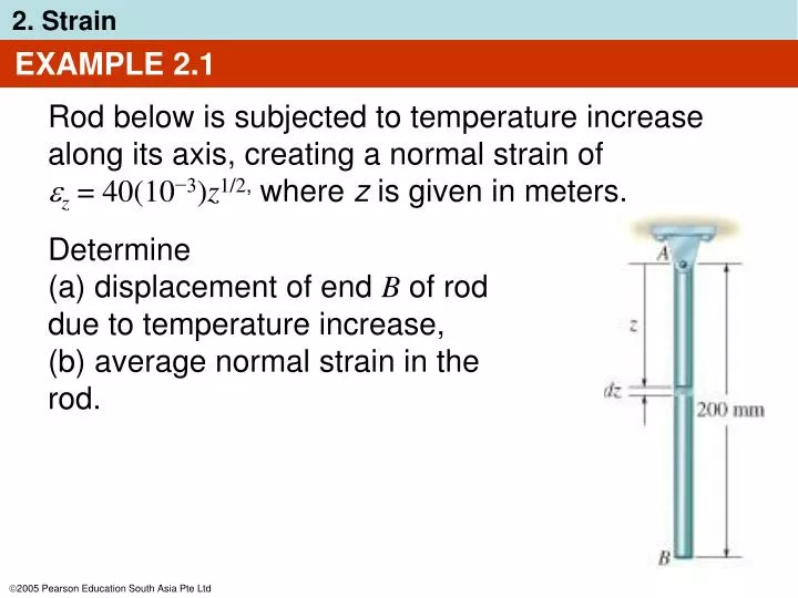
EXAMPLE 2.1. Rod below is subjected to temperature increase along its axis, creating a normal strain of z = 40(10 −3 ) z 1/2 , where z is given in meters. Determine (a) displacement of end B of rod due to temperature increase, (b) average normal strain in the rod. EXAMPLE 2.1 (SOLN).

E N D
EXAMPLE 2.1 Rod below is subjected to temperature increase along its axis, creating a normal strain of z = 40(10−3)z1/2, where z is given in meters. Determine (a) displacement of end B of rod due to temperature increase, (b) average normal strain in the rod.
EXAMPLE 2.1 (SOLN) • Since normal strain reported at each point along the rod, a differential segment dz, located at position z has a deformed length: dz’ = [1 + 40(10−3)z1/2] dz
0.2 m z’ = ∫0 [1 + 40(10−3)z1/2] dz = z+ 40(10−3)(⅔ z3/2)|0 = 0.20239 m 0.2 m EXAMPLE 2.1 (SOLN) • Sum total of these segments along axis yields deformed length of the rod, i.e., Displacement of end of rod is ΔB = 0.20239 m − 0.2 m = 2.39 mm ↓
Δs’ − Δs 2.39 mm = = 0.0119 mm/mm avg = 200 mm Δs EXAMPLE 2.1 (SOLN) • Assume rod or “line segment” has original length of 200 mm and a change in length of 2.39 mm. Hence,
EXAMPLE 2.3 Plate is deformed as shown in figure. In this deformed shape, horizontal lines on the on plate remain horizontal and do not change their length. • Determine • average normal strain along side AB, • average shear strain in the plate relative to x and y axes
AB’ = √ (250 − 2)2 + (3)2 = 248.018 mm EXAMPLE 2.3 (SOLN) (a) Line AB, coincident with y axis, becomes line AB’ after deformation. Length of line AB’ is
AB’ − AB 248.018 mm − 250 mm (AB)avg = = 250 mm AB = −7.93(10−3) mm/mm EXAMPLE 2.3 (SOLN) • Therefore, average normal strain for AB is, Negative sign means strain causes a contraction of AB.
) ( 3 mm γxy = tan−1 = 0.0121 rad 250 mm − 2 mm EXAMPLE 2.3 (SOLN) • Due to displacement of B to B’, angle BAC referenced from x, y axes changes to θ’. Since γxy = /2 − θ’, thus
CHAPTER REVIEW • Loads cause bodies to deform, thus points in the body will undergo displacements or changes in position • Normal strain is a measure of elongation or contraction of small line segment in the body • Shear strain is a measure of the change in angle that occurs between two small line segments that are originally perpendicular to each other
CHAPTER REVIEW • State of strain at a point is described by six strain components: • Three normal strains: x, y, z • Three shear strains: γxy, γxz, γyz • These components depend upon the orientation of the line segments and their location in the body • Strain is a geometrical quantity measured by experimental techniques. Stress in body is then determined from material property relations
CHAPTER REVIEW • Most engineering materials undergo small deformations, so normal strain << 1. This assumption of “small strain analysis” allows us to simplify calculations for normal strain, since first-order approximations can be made about their size