Download
1 / 58
620 likes | 1.11k Views
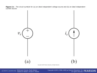
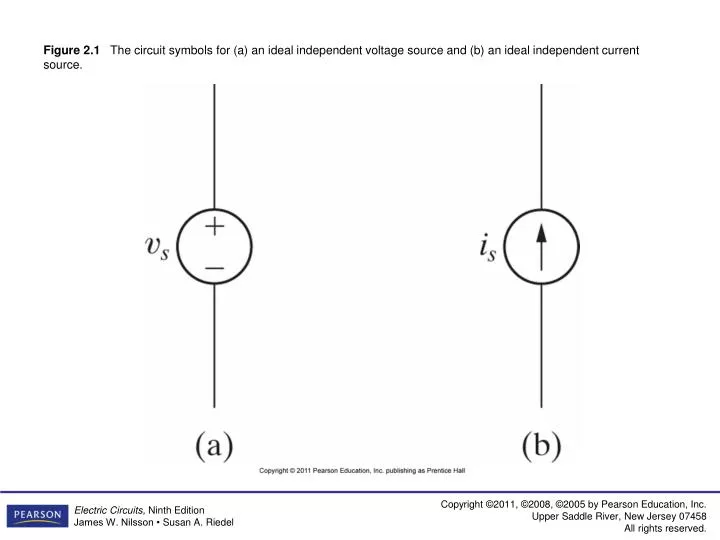
Figure 2.1 The circuit symbols for (a) an ideal independent voltage source and (b) an ideal independent current source.

E N D
Figure 2.1 The circuit symbols for (a) an ideal independent voltage source and (b) an ideal independent current source.
Figure 2.2 The circuit symbols for (a) an ideal dependent voltage-controlled voltage source, (b) an ideal dependent current-controlled voltage source, (c) an ideal dependent voltage-controlled current source, and (d) an ideal dependent current-controlled current source.
Figure 2.5 The circuit symbol for a resistor having a resistance R.
Figure 2.6 Two possible reference choices for the current and voltage at the terminals of a resistor, and the resulting equations.
Figure 2.9 A flashlight can be viewed as an electrical system.
Figure 2.10 Circuit symbols. (a) Short circuit. (b) Open circuit. (c) Switch.
Figure 2.14 (a) The values of υt versus it for the device in Fig. 2.13. (b) The circuit model for the device in Fig. 2.13.
Figure 2.15 Circuit model of the flashlight with assigned voltage and current variables.
Figure 2.19 The circuit shown in Fig. 2.18, with the unknowns i1, υo, and υ1 defined.
Figure 2.21 (a) The graph of υt versus it for the device in Fig. 2.20(a). (b) The resulting circuit model for the device in Fig. 2.20(a), connected to a 10 Ω resistor.
Figure 2.25 (a) A human body with a voltage difference between one arm and one leg. (b) A simplified model of the human body with a voltage difference between one arm and one leg.