Download
1 / 57
570 likes | 777 Views
Self-Stabilizing Quad-Rotor Helicopter SSQUARe. Group 7 Daniel Goodhew Angel Rodriguez Jared Rought John Sullivan. Agenda. Project Motivation and Goals Project Specifications System Block Diagram Inertial Measurement Unit and Sensors Microcontroller User Interface Vehicle Body

E N D
Self-Stabilizing Quad-Rotor HelicopterSSQUARe Group 7 Daniel Goodhew Angel Rodriguez Jared Rought John Sullivan
Agenda • Project Motivation and Goals • Project Specifications • System Block Diagram • Inertial Measurement Unit and Sensors • Microcontroller • User Interface • Vehicle Body • Power • Problems • Administrative Details • Questions
Motivation and Goals • To create a fun and useful aerial vehicle • Cost will be moderate to low, but must not sacrifice quality of design • Must be lightweight • Unit will self-stabilize • Have live video streaming • Be controlled through an IPhone application
General Specifications • Weigh less than 1kg • Have 4 motors • Have 12 minutes of flight time • Be able to change motor speed at a rate of 50 Hz • Communicate with iPhone 4 times per second
Inertial Measurement Unit Goals and Objectives • Provide data regarding the orientation of the aircraft • Be able to track tri-axial rotations in a timely manner • Easily interface with microcontroller
IMU Specifications and Requirements • Track pitch, roll and yaw • At minimum, have a refresh rate of 50 Hz • Operate off a 610 mAh battery
Selection of Orientation Algorithm • Many approaches available • Simple control loop • Modeling Flight Dynamics • Draw backs • Not accurate enough to provide highly stable flight • Requires extensive modeling of aircraft and environment
Alternative Algorithm Selected: Directional Cosine Matrix (DCM) • Provides accurate orientation tracking • Loosely based of a flight control method developed for planes • Draw backs • Method is limited by the accuracy of the sensors • Gyro drift
DCM Explained • The earth’s reference frame is fixed • Each row represents a vector R
DCM Design • Using the kinematics of a rotating vector… • This equation can then be integrated to derive the tracking vector • Integration is done through numerical integration
DCM Design Equation becomes… r(0) = Starting vector value = Change in vector
DCM Design • Gyro measurements are taken in the aircraft’s frame of reference • A Rotation in the earth’s reference frame is equal and opposite a rotation in the aircraft’s frame of reference • Thus, we invert the sign of all the measurements
DCM Design • Initial term brought into matrix • Utilizing these equations, we then present the matrix formulation…
DCM Design: Issues • Gyroscopic drift errors attributed to MEMS based electronic gyroscopes • Accumulation of numerical errors
DCM Design: Solutions • Utilize sensor blending to mitigate gyro drift • Accelerometer is used to correct pitch and roll drift • Magnetometer is used to correct yaw drift • Renormalization of the DCM is used to correct numerical integration error accumulation
DCM Renormalization • Compute dot product of X and Y rows of DCM • This should normally be zero because the X and Y axes are orthogonal • Recall that… • A value other than zero signifies error in measurement
DCM Renormalization To find Z, we utilize the property of the cross product…
DCM: Renormalization • The orthogonal vectors must be scaled to ensure a magnitude of one • Use a Taylor expansion
DCM: Drift Correction • Accelerometer corrects pitch and roll drift
DCM: Yaw Drift Correction • Magnetometer is used to correct yaw drift • Produces heading • Reference vector is taken during initialization • Used to produce yaw error
PI Controller • Error values processed through a PI controller
Using DCM When rZX and rZY = 0, the helicopter is level
Using DCM • Pitch and roll control • No Commands, aircraft auto levels • Commands alter this state • Default Pitch and Roll angle • Yaw control • No command, no yaw adjustment • Default yaw adjust rate
Sensor selection: Gyroscope • Originally used a 2-axis and 1-axis analog sensors • New design utilizes a 3-axis digital gyro • ITG-3200 from Inversense
Sensor selection: Accel • Selected ADXL335 • 3-axis analog accelerometer • Readily available from Sparkfun
Sensor selection: Magnetometer • Selected HMC5843 • 3-axis digital Magnetometer • Readily available from Sparkfun • Not tilt compensated
Ultrasonic Sensor • Must be able to sense the ground up to 15ft away • Determine the distance by dividing the voltage out by 1024 and multiplying by 3.2mV to find out the range in centimeters • max range of 600cm
Microcontroller Requirements • I2C and 3 ADC channels to receive and convert IMU • Timer with four PWM outputs to control motors • UART to communicate with Wi-Fi module • Fast enough to run the DCM and control loop once every PWM period of 20 ms. • 64 KB minimum to store all the code
Microcontroller Selection Selected STM32F103CBT6 • Reasons for Selection: • Has a lot processing power at 72 Mhz • Has 128 KB of onboard flash storage • Used in a project implementing DCM • Other Information • ARM Cortex-M3 • Produced by STMicoelectronics • Received free samples from STMicroelectronics
STM32 Development Hardware • A JTAG interface was used to program and debug the STM32 • Olimex USBTINY • Uses USB Port to interface to PC • Development Board • Olimex STM32-H103 • Inexpensive ~$40 • Uses JTAG • Powered from USB • Small size
Software Development • C used as programming language • STMicroelectronics STM32 Library • Eclipse used as IDE • OpenOCD used to debug code running on STM32 • Source code compiled with Codesourcery’s G++ Lite GNU tool chain • All software tools are open source and are free to use
Control Board Schematic: Microcontroller interface and sensors
Communication Overview • Use Wi-Fi to send and receive data between the copter and iPhone • The iPhone receives the height data coming from the copter • The iPhone sends the copter the controls that the user is inputting
iPhone Interface • An iPhone is used to control the Quad-copter through an iPhone application • The Touch based functions of the iPhone are used to control the copter • Will show DCM angle values, height, orientation correction values, and motor throttle control
Software • iPhone application was written in Objective C • Objective C is an object oriented version of C by Apple • The application was developed using Xcode IDE and through the Interface Builder • The Interface Builder provides easy design capabilities such as drag and drop functionality
Package Structure • From iPhone to Copter • LXXRXXBXXF • Left Slider Value, Right Slider Value, Bottom Slider Value, Control Flag • From Copter to iPhone • Altitude of copter • DCM angles
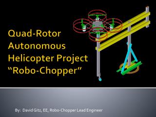
Vehicle Body • Goals • Lightweight • Reasonably priced • Impact resistant • Specifications • Under 1 kg • 25” x 25” x 10”
Vehicle Construction • The frame is constructed with four aluminum tubular arms connected in the center by a four-way PVC connector. • Motors are bolted to the tubes with a three-sided bracket in between to provide stability. • All wiring and ESCs are placed inside the tubing. • The PCB and landing base are glued in place. PCB
Motors • Goals • Thrust of 1.5 times quad copter weight • Equilibrium between current draw and thrust • Specifications • 7.5 A maximum current draw • Up to 400 g thrust • Controlled with electronic speed controllers (ESC) • A 50 Hz signal with pulse width modulation (PWM) controls the current draw of the motors • 1 ms PWM = 0 throttle • 2 ms PWM = full throttle • 10 A capacity
Power Specifications • Provide 11.1V at up to 7.5 A for 12 minute flight time. • Provide 3.3 V for board components. • Weigh under 400 grams.
Power Design • Two batteries are used to maintain a clean power source for the PCB. • 4400mAh LiPo for the motors. • Will run for 8.8 minutes at max current draw. • Sensor will indicate when battery is low. • 610mAh Lipo for the PCB. • Will run for much longer than the motors. • We are using two TLV1117-33 linear voltage regulators to provide separate digital and analog power sources. The ground plane is also divided accordingly.
Current Draw • Estimated maximum current for each component is used to determine battery size necessary.
Control Board • Two 3.3V voltage regulators are next to power switch • Headers connect to outside components • Dimensions: 3 X 4 inches • Components mounted by hand • Mounted to frame on top of plastic stand-offs • Fabricated for free from Daniel’s employer Intersil.