Download
1 / 27
270 likes | 428 Views
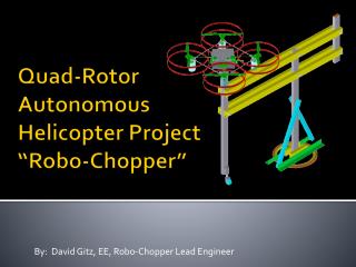
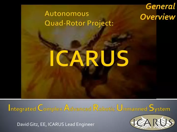
General Overview. David Gitz, EE, ICARUS Lead Engineer. ICARUS. Autonomous Quad-Rotor Project:. I ntegrated C omplex A dvanced R obotic U nmanned S ystem. Core Team. Ben Wasson Masters Student ICARUS Business Manager David Gitz Electrical Engineer ICARUS Lead Engineer

E N D
General Overview David Gitz, EE, ICARUS Lead Engineer ICARUS AutonomousQuad-Rotor Project: Integrated Complex Advanced Robotic Unmanned System
Core Team • Ben Wasson • Masters Student • ICARUS Business Manager • David Gitz • Electrical Engineer • ICARUS Lead Engineer • Michael Welling • PhD Candidate • ICARUS Systems Engineer • James Chaklos • Masters Student • ICARUS Test-Stand Engineer • Steve Warren • Computer Engineer • ICARUS Communications Engineer
Satellite Teams • Washington University UAV Team • SIU-Carbondale Senior Design (pending)
Topics: Applications The Future System Description Capabilities Competitor Analysis
Applications Civil Inspection Residential Inspection Large Building Inspection
Future of Quad-Rotor’s V-44 Bell/Boeing Pending ArduCopter DraganFlyer v6 V-22 Osprey Bell Helicopter Boeing Rotorcraft Systems 2007 ICARUS FUTURE PAST
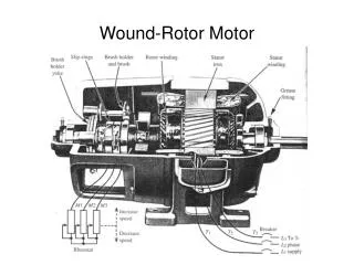
Vehicle • Quad-Rotor design – Offers simpler control system with fewer moving parts than a single rotor helicopter and minor reduction in lift capacity
Vehicle • 2 “Brains”, 1 SoM Board and 1 Parallax PropellerTM uC • SoM handles waypoint navigation, mission planning, vehicle health. • PropellerTM uC handles PWM generation. • In the event of an in-air mishap, PropellerTM uC can take over Vehicle and land safely.
Vehicle Specifications • Sensors: 3-Axis Accelerometer, 3-Axis Gyroscope, 3-Axis Magnetometer (INU), Digital Compass, Altimeter, GPS, 7 Ultrasonic Sensors • Power: 8 Brushless DC 200 Watt Motors, 4 Micro Servo’s, 2 Lithium-Ion 11.1V 5 Amp-Hours Batteries, 4 18A Electronic Speed Controllers, 5V and 3.3V Linear Voltage Regulators. • Control: SoM Controller (Primary), Propeller Controller (Secondary), custom PCB. • Communications: Xbee Radio for Command/Control, Video Transmitter, Wi-Fi (Field programming, tentative). • Fabrication: ~50% COTS, ~50% produced by MakerBot/Ponoku.
Movement CW Pitch CCW Roll Yaw CW CW: Puller CCW: Pusher Forward CCW
Test-Fixture Attachment System Recovery System Safety System Camera System Heat Removal System Prototype Systems Landing Pad
RCU • Custom PCB inside Xbox-360 Controller • Features Mode and Error Display, Vehicle Battery Indicator, Force-Feedback and 5 hours of continuous operation.
RCU Specifications • Communications: XBee Radio for Command/Control • Input/Output: 9 Switches/Buttons, 2 Dual-Axis Joysticks, GPS Sensor, 10-Segment LED, LCD Screen, Vibrating Motors. • Power: 2 Ni-Mh AA Batteries, 3.3 and 5V Boost Converters.
GCS • Includes computer, touch-screen monitor and batteries for field operation. • Communications Radio and Video Receiver • Heavy-duty field transportable case
GCS Interface • Manual Control • Vehicle Sensor Display • Vehicle Health/Feedback System • Autonomous Control • Set, Transmit Waypoints • Communications • View Network Status • Configuration/Debugging • Google Earth Integration • Fully controllable Google Earth (location search, zoom, pan, etc). • View Waypoints and Vehicle Location/Path
GCS Specifications • Software: National Instruments LabView integrated with Google Earth mapping software. • Power: 2 12V 26Amp-Hour Batteries, 120V AC Power Inverter, Vehicle battery fast charger. • Communications: XBee Radio for Command/Control, Video Receiver
Test-Stand • Used for Vehicle Calibration and Capacity measurements • Able to Pivot vertically, rotate continuously and pitch/yaw/roll on Test-Fixture Assembly • Power applied to Vehicle via Slip-Ring – No tangled wires
InmarSat Satellite GPS Satellite Zigbee Wi-Fi Cellular SATCOM 900 MHz (Video) Internet Connectivity Diagram Vehicle WAN Cellular Network Ground Entry Point RCU GCS
InmarSat Satellite GPS Satellite Command/Control Video GPS Services Diagram Vehicle WAN Cellular Network Ground Entry Point RCU GCS
System Specifications • Range: ~1.5 km LOS (~3km with Xbee Mesh Network) • Duration: • Vehicle: ~12 min (100% Throttle) , ~20 min ( Hover) • RCU: ~4-6 hrs • GCS: ~4-6 hrs (including field charging Vehicle) • Speed: ~2 - 4 kph • Weight: ~5.5 lbs • Size: 48” x 48” x 10.5” • Propeller Rotation: Max: 3,000 RPM • Vertical Thrust: ~7.8 lbs
Questions? • Contact: • David Gitz: david.gitz@icarusuav.com • Ben Wasson: ben.wasson@icarusuav.com