Download
1 / 23
250 likes | 461 Views
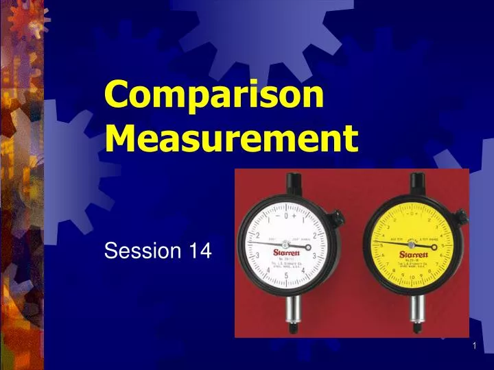
Comparison Measurement. Session 14. Comparison Measurement. Process consisting of comparing measurement of part to known standard or master of exact dimension required Comparators Any instrument used to compare size of workpiece to known standard

E N D
Comparison Measurement Session 14
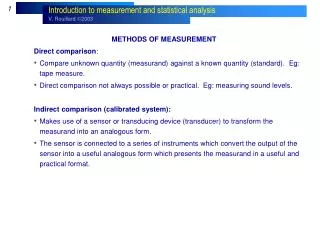
Comparison Measurement • Process consisting of comparing measurement of part to known standard or master of exact dimension required • Comparators • Any instrument used to compare size of workpiece to known standard • Incorporate some means of amplification to compare part size to set standard • Standard usually gage blocks
Dial Indicators • Used to compare sizes and measurements to known standard and check alignment of machine tools, fixtures, and workpieces prior to machining • Many work on gear and rack principle • Rack cut on plunger or spindle is in mesh with a pinion which is connected to a gear train • Any movement of spindle magnified and transmitted to pointer over graduated dial
Dial Indicators • Generally two types • Continuous-reading dial indicator • Numbered clockwise for 360º • Regular-range • Only 2 ½ revolutions • Long-range indicator • Digital and used to indicate table travel
Dial Indicators • Generally two types • Dial test indicator • Reads both right and left from 0 • Equipped with tolerance pointers
Dial Test Indicators • Perpendicular dial test indicators • Have spindle at right angles to dial • Used in setting up lathe work, table alignment • Universal dial test indicator • Has contact point that may set through 180º arc • Used to check internal and external surfaces
Electronic Dial Indicators • Generally Round Face • Regular-range • One inch • 25 millimeters • Accuracies • Typically 0.000 05 in • Typically 0.000 1 mm
Indicator Magnetic Base Stand • Manual Indicator • Height adjustable • Magnetic Base • Allows setting indicator at different angles or positions
Dial Indicator Inspection Stand • Electronic Indicator • Height adjustable • Accommodates various size parts • Base Precision machined or ground granite
Measuring with a Dial Test Indicator and Height Gage • Clean face of surface plate and height gage • Mount dial indicator on movable jaw • Lower movable jaw until indicator point just touches top of gage block resting on surface plate • Tighten upper locking screw on vernier and loosen lower locking screw
Measuring with a Dial Test Indicator and Height Gage • Carefully turn adjusting nut until indicator needle registers ¼ turn • Turn bezel to set indicator to zero • Note reading on height gage and record it • Raise indicator to height of first location to measure
Measuring with a Dial Test Indicator and Height Gage • Adjust height gage until indicator reads zero • Note height gage reading againand record it • Subtract first reading from second