Download
1 / 34
440 likes | 602 Views
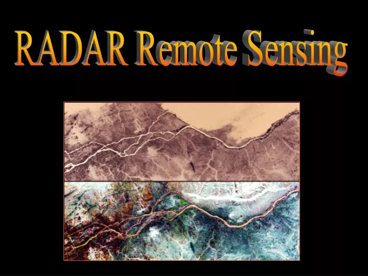
RADAR Remote Sensing. Introduction. A Quick Reminder Passive RS Systems: Record energy reflected (visible, NIR) and emitted (TIR) from the Earth’s surface Active RS Systems Transmit their own EM energy to Earth and record backscattered energy. Introduction.

E N D
Introduction • A Quick Reminder • Passive RS Systems: • Record energy reflected (visible, NIR) and emitted (TIR) from the Earth’s surface • Active RS Systems • Transmit their own EM energy to Earth and record backscattered energy
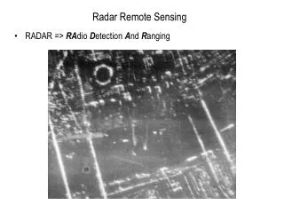
Introduction • Most widely used active RS systems • RADAR • Radio Detection and Ranging • Microwaves (long waves) • LIDAR • Light Detection and Ranging • Laser light waves (short waves) • Topographic mapping, etc. • SONAR • Sound Navigation and Ranging • Sound waves (long waves) • Bathymetric mapping, etc.
RADAR Basics • Two types of RADAR data collection systems • Active: • Record ‘artificially generated’ microwave energy • Passive: • Record microwave ‘naturally emitted’ microwave energy
History of RADAR RS • James Clerk Maxwell (1831-1879) • Provided mathematical descriptions of magnetic and electric fields associated with EM radiation • Heinrich R. Hertz (1857-1894) • Provided fundamental knowledge of creation and propagation of EM energy in microwave and radio portions of EMS • His studies on interaction of radio waves with metallic surfaces eventually facilitated the invention of radios and radars • Guglielmo M. Marconi (1874-1937) • Used above fundamental physics principles to construct the first antenna to transmit and receive radio waves • 1901: Radio waves across the Atlantic • 1909: Novel Prize in physics
History of RADAR RS • A. H. Taylor and L.C. Young • 1922 • Realized that radio signals might be useful for detecting the distance to ships at sea, etc. and both at night and in bad weather • Today, we use almost only microwaves but the term RADAR was never changed • 1935 • Combined antenna transmitter and receiver in one instrument • Groundwork for RADAR development during WW II for navigation and target location (back then: no RADAR imagery from air- or spacecraft)
History of RADAR RS • RADAR Imagery • SLAR: Side-Looking Air-borne Radar • Used since 1950s by military • Some systems declassified since the 1960s • Continuous-strip mapping capability • Reconnaissance over vast regions to the left or right of aircraft: Long-range standoff data collection • Radargrammetric measurement • Science of extracting quantitative geometric object information from RADAR imagery
History of RADAR RS • Two SLAR Types • Real Aperture Radar (AKA “brute force radar”) • Use antenna of fixed length (e.g., 1 – 2 m) • Synthetic Aperture Radar (SAR) (aperture = antenna) • Also use ‘fixed-length” antenna but are able to synthesize a much larger antenna (by sensing a greater number of beams) • Example: • An 11-m antenna on an orbital platform can be synthesized electronically to have a synthetic length of 15 km • The longer the antenna, the better the resolving power
History of RADAR RS • Since 1960s and 1970s • Various SARs launched for Earth resource reconnaissance • Particularly useful in areas that have a more or less perennial cloud cover (e.g., tropical areas) • 1978: SEASAT (USA) • 1981; 1984; 1994: SIR-A; SIR-B; SIR-C/X-SAR (USA) • 1991: ALMAZ-1(USSR) • 1991; 1994: ERS-1; ERS-2 (ESA) • 1992: JERS-1(Japan) • 1995; 2006: RADARSAT; RADARSAT2 (Canada) • 2000: SRTM (USA) • 2002: Envisat; ASAR (ESA)
Advantages of RADAR RS • All-weather RS system • Certain microwave frequencies penetrate cloud cover • Provides synoptic views of large areas for mapping • 1:10,000 – 1:400,000 • Coverage can be obtained at user-specific times • Day and night • Provides different perspectives that cannot always be obtained using aerial photography • Permits imaging at shallow look angles • Angle of illumination can be controlled (has its own illumination) • Provides information on surface roughness, dielectric properties, and moisture content • Senses in wavelengths outside the optical regions of the EMS,
Advantages of RADAR RS • May penetrate vegetation, sand, and snow surface layers • Enables resolutions to be independent of distance to object • Size of a resolution cell may be as small as 1 m • May produce images from different types of polarized energy • HH, HV, VV, VH • Has multi-frequency potential • May operate simultaneously in several wavelengths (frequencies) • Can measure ocean wave properties, even from orbital altitudes • Can produce overlapping images suitable for stereoscopic viewing • Can produce overlapping images suitable for radargrammetry • Supports interferometric operation using two antennas • 3-D mapping • Analysis of incident-angle signatures of objects
Disadvantages of RADAR RS • Can be very noisy and difficult to classify • Large amounts of geometric relief displacement • Geometric relief displacement inconsistent across the image
RADAR: How does it work? • Microwave energy is transmitted toward an area from an antenna in very short bursts or pulses • Energy is reflected off of the area (backscattered) and recorded at the same antenna after a period of time Propagation of one radar pulse
RADAR: How does it work? • Strength (detection) and time delay (ranging) of return signals is measured • Range or distance between the transmitter and the area are inferred from time elapsed between transmission and reception Resulting antenna return
Typical SLAR System Components Canberra IFSAR System Layout (Source: Original figure by H.A.Malliot, High Altitude Mapping Missions, Inc.)
Wavelength, Frequency, Pulse Length • Pulse of EM radiation transmitted through antenna • Has a specific wavelength • Much longer than TIR • Measured in centimeters (cm) • Names of radar wavelengths: • Alphabetic descriptor, not actual wavelength or frequency • Relicts of secret work on radar RS in WW II • Has a specific duration • Pulse length • Measured in microseconds (msec)
Wavelength, Frequency, Pulse Length • Ka, K, and Ku bands: • Shortest wavelengths • Partially absorbed by water vapor, thus limiting cloud penetration • Used by ground-based weather radars to track cloud cover and precipitation • X-band(SIR-C; SRTM) • Shortest wavelength used by any orbital/ sub-orbital imaging radar • C-band (SIR-C; ERS 1 & 2; RADARSAT 1 & 2; SRTM; Envisat, ASAR) • S-band (ALMAZ-1) • L-band(SEASAT, SIR-A, B, C; JERS-1) • P-band • Longest radar wavelengths
Azimuth, Range Direction, etc. • Ka, K, and Ku bands: • Shortest wavelengths • Partially absorbed by water vapor, thus limiting cloud penetration • Used by ground-based weather radars to track cloud cover and precipitation • X-band(SIR-C; SRTM) • Shortest wavelength used by any orbital/ sub-orbital imaging radar • C-band (SIR-C; ERS 1 & 2; RADARSAT 1 & 2; SRTM; Envisat, ASAR) • S-band (ALMAZ-1) • L-band(SEASAT, SIR-A, B, C; JERS-1) • P-band • Longest radar wavelengths
Look angle Φ Slant range Incident angle Nadir θ Swath Other Important Parameters • Azimuth Direction; Range Direction; Depression Angle; Look Angle; Incident Angle; Polarization
Look angle Φ Slant range Incident angle Nadir θ Swath System Resolution Other Important Parameters • Pulse length determines range resolution • Beam width determines azimuth resolution
Other Important Parameters • Azimuth Direction • Straight line in which the aircraft travels • Range / Look Direction • Direction in which active microwave energy illuminates strips of the terrain (orthogonal to the aircraft’s azimuth direction) • Near-range: terrain illuminated nearest the aircraft • Far-range: terrain illuminated farthest away from the aircraft • Significantly affects feature interpretation • Objects that trend (or strike) in a direction perpendicular to the range direction are more enhanced/emphasized than objects that lie parallel to it
Other Important Parameters • Effect of Range Direction on Radar Imagery • Example: X-band image of the Kaduna State in Nigeria East-west azimuth direction with RADAR looking south East-west azimuth direction with RADAR looking north • Note: Orient image so that the look direction is toward you. That way, the shadows fall toward you, keeping you from experiencing pseudoscopic illusion.
Other Important Parameters • Depression Angle (γ) • Angle between a horizontal plane extending out from the aircraft fuselage and the EM pulse of energy from the antenna along the radar line-of-sight to a specific point on the ground • Varies from a near-range to a far-range depression angle • Look Angle (Φ) • Angle between the vertical from the antenna to the ground and the radar line-of-sight • Varies from a near-range to a far-range look angle • Complement of the depression angle
Local slope angle, α Scattering surface Other Important Parameters • Incident Angle (θ) • Angle between the radar pulse of energy and a line perpendicular to the Earth’s surface where it makes contact • Complement of the depression angle where the terrain is flat (often assumed in radar studies) • Incident angle in terms of the relationship between radar beam and surface slope: Vertical Normal to surface Incident angle, θ Radar wave Local incident angle
Other Important Parameters • Polarization • Unpolarized energy vibrates in all possible directions perpendicular to the direction of travel • Radar antennas send and receive polarized energy( Pulse of energy is filtered) • Four Polarizations • Like-polarized (co-polarized): • Send and receive horizontally polarized energy (HH) • Send and receive vertically polarized energy (VV) • Cross-polarized: • Send horizontal and receive vertically polarized energy (HV) • Send vertical and receive horizontally polarized energy (VH)
RADAR Polarization Cinder cone and basalt lava flow, AZ
Slant- vs. Ground Range Geometry • Uncorrected imagery is displayed in slant-range geometry • Based on actual distance from the radar to features in the scene • Near-range objects are more compressed than far-range objects • May be converted to ground-range geometry so that features in the scene are in their proper planimetric position (See book.)
RADAR Issues • Geometric distortions exist in almost all RADAR imagery • No problem in flat terrain • Simple algorithms for converting slant-range to ground-range geometry • Problem in variable terrain • RADAR image is formed in the range (cross-track) direction • The higher the object, the closer it is to the antenna, and the sooner it is detected on the radar image Displacement toward the antenna (vs. air photos where relief displacement is away from the PP) • Foreshortening & Layover = Elevation-induced distortions • Shadows • Speckle
RADAR & Topography • Foreshortening • In high relief areas, slopes facing the sensor will appear compressed and their lengths will be incorrect
RADAR & Topography • Layover • Extreme case of foreshortening • When the return signal from the top of a feature is received before that of the base • Object will appear to lean toward the sensor
RADAR & Topography • Radar Shadow • The down range dimension of a tall object is not illuminated by the sensor so that no energy is available to be backscattered
RADAR & Topography • Speckle • Grainy salt-and-pepper pattern in RADAR imagery • Due to coherent nature of the RADAR wave, which causes random constructive and destructive interference, hence random bright and dark areas in an image • Can be reduced but at the cost of degraded resolution (LAB) 1-look radar image 4-look radar image 16-look radar image ------------Radar speckle reduction using multiple-look techniques ------------