Download
1 / 57
670 likes | 1.04k Views
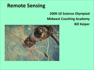
Remote Sensing. Image data processing. Data Collection. In Situ data Field sampling, laboratory sampling, combination of both Used to calibrate the sensor data and perform unbiased accuracy assessment of final results GPS – ideal tool to gather positional data x, y, z

E N D
Remote Sensing Image data processing
Data Collection • In Situ data • Field sampling, laboratory sampling, combination of both • Used to calibrate the sensor data and perform unbiased accuracy assessment of final results • GPS – ideal tool to gather positional data x, y, z • Remotely Sensed Data • Format and quality of remotely sensed data vary widely. • Two classes of variables can be remotely sensed • Biophysical variables - measure directly (e.g., sea surface temperature) • Hybrid variables – measure more than one (e.g., detect vegetation stress) • 4 types of resolution that effect quality and nature of data a sensor collects: radiometric, spatial, spectral and temporal
Overview • satellite systems • image processing example • software and data exchange • new developments
Bands or Layers Every image is composed of bands or layers. Each band is a set of data file values for a specific portion of the electromagnetic spectrum of reflected light or emitted heat.
Bands or Layers (Contd) Every band is viewable as a separate image.Each band provides greater insight as to the composition of the imaged area.
Band Combinations 3,2,1 4,3,2 5,4,3
Data Analysis • Analog Image Processing • Elements of image interpretation • Digital Image Processing • Preprocessing • Information Ehancement • Information Extraction
Image Interpretation And Analysis • In order to take advantage of and make good use of remote sensing data, we must be able to extract meaningful information from the imagery. • This is done through Image Interpretation and Analysis
Image Interpretation And Analysis • Interpretation and analysis of remote sensing imagery involves the identification and/or measurement of various targets in an image in order to extract useful information about them
Image Interpretation And Analysis • Targets in remote sensing images may be any feature or object which can be observed in an image, and have the following characteristics: a) Targets may be a point, line, or area feature. This means that they can have any form, from a bus in a parking lot or plane on a runway, to a bridge or roadway, to a large expanse of water or a field. b) The target must be distinguishable; it must contrast with other features around it in the image.
Image Interpretation And Analysis Much interpretation and identification of targets in remote sensing imagery is performed manually or visually when we have data in ANALOG format.
Image Interpretation And Analysis • Remote sensing images can also be represented in a computer as arrays of pixels, with each pixel corresponding to a digital number, representing the brightness level of that pixel in the image known as Digital format . • When remote sensing data are available in digital format, digital processing and analysis may be performed using a computer.
Visual Interpretation Elements of Visual Interpretation : • tone • shape • size • pattern • texture • shadow, and • association
Elements of Visual Interpretation TONE refers to the relative brightness or colour of objects in an image. Generally, tone is the fundamental element for distinguishing between different targets or features. Variations in tone also allows the elements of shape, texture, and pattern of objects to be distinguished.
Elements of Visual Interpretation • Shape refers to the general form, structure, or outline of individual objects. • Shape can be a very distinctive clue for interpretation. • Straight edge shapes typically represent urban or agricultural (field) targets, while natural features, such as forest edges, are generally more irregular in shape, except where man has created a road or clear cuts
Elements of Visual Interpretation • Size of objects in an image is a function of scale. It is important to assess the size of a target relative to other objects in a scene, as well as the absolute size, to aid in the interpretation of that target. • For example, large buildings such as factories or warehouses would suggest commercial property, whereas small buildings would indicate residential use
Elements of Visual Interpretation • Pattern refers to the spatial arrangement of visibly discernible objects. • Typically an orderly repetition of similar tones and textures will produce a distinctive and ultimately recognizable pattern. • Orchards with evenly spaced trees, and urban streets with regularly spaced houses are good examples of pattern.
Elements of Visual Interpretation • Texture refers to the arrangement and frequency of tonal variation in particular areas of an image. • Rough textures would consist of a mottled tone where the grey levels change abruptly in a small area, whereas smooth textures would have very little tonal variation. • Smooth textures are most often the result of uniform, even surfaces, such as fields, asphalt, or grasslands. • Texture is one of the most important elements for distinguishing features in radar imagery.
Elements of Visual Interpretation • Shadow is also helpful in interpretation as it may provide an idea of the profile and relative height of a target or targets which may make identification easier. • Shadows can also reduce or eliminate interpretation in their area of influence, since targets within shadows are much less (or not at all) discernible from their surroundings. • Shadow is also useful for enhancing or identifying topography and landforms, particularly in radar imagery.
Elements of Visual Interpretation • Association takes into account the relationship between other recognizable objects or features in proximity to the target of interest. • The identification of features that one would expect to associate with other features may provide information to facilitate identification.
Image processing steps • geometric and radiometric correction • atmospheric correction • subsetting, mosaic, enhancement • geo-coding (map projection, spheroid, units) • parameter extraction (multivariate statistics, regression model, physical model etc.) • post-processing (filtering, grouping, data reduction) • Raster GIS: focal or global operations • hybrid GIS: zonal/region-based operations, spatial statistics
Digital Image Processing • In today's world of advanced technology where most remote sensing data are recorded in digital format, virtually all image interpretation and analysis involves some element of digital processing. • Digital image processing may involve numerous procedures including formatting and correcting of the data, digital enhancement to facilitate better visual interpretation, or even automated classification of targets and features entirely by computer.
Digital Image Processing Digital image processing may involve numerous procedures including formatting and correcting of the data, digital enhancement to facilitate better visual interpretation, or even automated classification of targets and features entirely by computer
Digital Image Processing Most of the common image processing functions available in image analysis systems can be categorized into the following four categories: • Preprocessing • Image Enhancement • Image Transformation • Image Classification and Analysis
Preprocessing Preprocessing functions involve those operations that are normally required prior to the main data analysis and extraction of information, and are generally grouped as radiometric or geometric corrections.
Preprocessing • Radiometric corrections include correcting the data for sensor irregularities and unwanted sensor or atmospheric noise, and converting the data so they accurately represent the reflected or emitted radiation measured by the sensor. • Geometric corrections include correcting for geometric distortions due to sensor-Earth geometry variations, and conversion of the data to real world coordinates (e.g. latitude and longitude) on the Earth's surface.
Image Enhancement To improve the appearance of the imagery to assist in visual interpretation and analysis. Examples of enhancement functions include contrast stretching to increase the tonal distinction between various features in a scene, and spatial filtering to enhance (or suppress) specific spatial patterns in an image.
Image Transformation Image transformations are operations similar in concept to those for image enhancement. However, unlike image enhancement operations which are normally applied only to a single channel of data at a time, image transformations usually involve combined processing of data from multiple spectral bands. Arithmetic operations (i.e. subtraction, addition, multiplication, division) are performed to combine and transform the original bands into "new" images which better display or highlight certain features in the scene.
Image Classification and Analysis • Image classification and analysis operations are used to digitally identify and classify pixels in the data. • Classification is usually performed on multi-channel data sets (A) and this process assigns each pixel in an image to a particular class or theme (B) based on statistical characteristics of the pixel brightness values.
Image Classification and Analysis • There are a variety of approaches taken to perform digital classification. • Two generic approaches which are used most often, namely supervised and unsupervised classification.
Preprocessing Image pre-processing has a number of component parts: • Radiometric correction • Geometric correction • Noise removal
Radiometric Correction • Radiometric corrections may be necessary due to variations in scene illumination and viewing geometry, atmospheric conditions, and sensor noise and response. • Each of these will vary depending on the specific sensor and platform used to acquire the data and the conditions during data acquisition. • Also, it may be desirable to convert and/or calibrate the data to known (absolute) radiation or reflectance units to facilitate comparison between data
Geometric Registration Process • Involves identifying the image coordinates (i.e. row, column) of several clearly discernible points, called ground control points (or GCPs), in the distorted image (A - A1 to A4), and matching them to their true positions in ground coordinates (e.g. latitude, longitude). • The true ground coordinates are typically measured from a map (B - B1 to B4), either in paper or digital format • This is image-to-map registration
Atmospheric Correction • LANDSAT-TM without and with atmospheric correction
Image Enhancement • Enhancements are used to make it easier for visual interpretation and understanding of imagery. • The advantage of digital imagery is that it allows us to manipulate the digital pixel values in an image • There are three main types of image enhancement: • Contrast enhancement • Spatial feature enhancement • Multi-image enhancement
Contrast Enhancement Image Histogram • In raw imagery, the useful data often populates only a small portion of the available range of digital values (commonly 8 bits or 256 levels). • Contrast enhancement involves changing the original values so that more of the available range is used, thereby increasing the contrast between targets and their backgrounds. • The key to understanding contrast enhancements is to understand the concept of an image histogram
Image Histogram A histogram is a graphical representation of the brightness values that comprise an image. The brightness values (i.e. 0-255) are displayed along the x-axis of the graph. The frequency of occurrence of each of these values in the image is shown on the y-axis
Histogram Stretch • By manipulating the range of digital values in an image, graphically represented by its histogram, we can apply various enhancements to the data. • There are many different techniques and methods of enhancing contrast and detail in an image; we will cover only a few common ones here. • Linear Stretch • Histogram Equalised Stretch
Linear Stretch A linear stretch involves identifying lower and upper bounds from the histogram (usually the minimum and maximum brightness values in the image) and applying a transformation to stretch this range to fill the full range.
Histogram Equalised Stretch If the input range is not uniformly distributed. In this case, a histogram-equalised stretch may be better. This stretch assigns more display values (range) to the frequently occurring portions of the histogram. In this way, the detail in these areas will be better enhanced relative to those areas of the original histogram where values occur less frequently
Spatial feature enhancement Spatial Filtering • Spatial filtering encompasses another set of digital processing functions which are used to enhance the appearance of an image. • Spatial filters are designed to highlight or suppress specific features in an image based on their spatial frequency. • Spatial frequency is related to the concept of image texture, and refers to the frequency of the variations in tone that appear in an image
Spatial Filtering A common filtering involves moving a 'window' of a few pixels in dimension (e.g. 3x3, 5x5, etc.) over each pixel in the image, applying a mathematical calculation using the pixel values under that window, and replacing the central pixel with the new value.
Spatial Filtering A low-pass filter is designed to emphasise larger, homogeneous areas of similar tone and reduce the smaller detail in an image. Thus, low-pass filters generally serve to smooth the appearance of an image.
Spatial Filtering A high-pass filter does the opposite, and serves to sharpen the appearance of fine detail in an image.
Spatial Filtering Directional or edge detecting filters highlight linear features, such as roads or field boundaries. These filters can also be designed to enhance features which are oriented in specific directions and are useful in applications such as geology, for the detection of linear geologic structures.
Colour Composites • A colour composite is a colour image produced through optical combination of multiband images by projection through filters. • True Colour Composite: A colour imaging process whereby the colour of the image is the same as the colour of the object imaged. • False Colour Composite: A colour imaging process which produces an image of a colour that does not correspond to the true colour of the scene (as seen by our eyes).