Download
1 / 34
350 likes | 363 Views
Shunt Capacitor Switching For Power Factor Improvement. Clayton H Reid. Power Factor. Kw is productive power Kvar is non productive. Industrial Plant Electrical Load. Induction Motors Induction Furnaces Fluorescent Lighting. Advantages of Installing Capacitors. Improved Power Factor

E N D
Shunt Capacitor Switching ForPower Factor Improvement Clayton H Reid
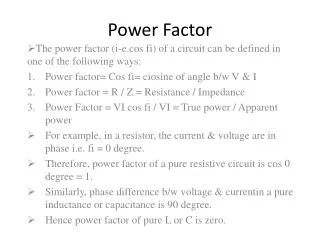
Power Factor Kw is productive power Kvar is non productive
Industrial Plant Electrical Load • Induction Motors • Induction Furnaces • Fluorescent Lighting
Advantages of Installing Capacitors • Improved Power Factor • Released System Capacity • Improved Motor and Lighting Performance • Reduced Current and Losses • Decreased Transformer Losses
Shunt-capacitor Banks • Automatic switching of capacitor banks • Voltage Control-a voltage sensitive relay is used which responds to changes in line voltage • Current Control-a current sensitive relay is used which responds to changes in line current • Kilovar Control-a kilovar relay is used which responds to changes in reactive loads
Capacitors Switched with Motor • Another means of obtaining automatic switching is to connect the capacitor to the motor and switch the motor and capacitor as a single unit
Capacitors Switched with Motor • The importance of selecting the correct size of capacitor to be switched with a given motor load • Location of capacitor connected points • Capacitor switching for special motors and for special motor-starting applications
Capacitors Switched with Motor • Transient inrush current and frequency for the following cases: • When a single capacitor is energized on a system • When a capacitor is energized in parallel with capacitor banks already connected • Effect of transient currents on contactors • Use of air-core reactors to limit transient current in parallel switching of capacitors
Overvoltage Due To Excessive Capacitance • Capacitor connected to the motor and starter de-energized, motor acts as an induction generator with shunt capacitor excitation
Maximum Voltage Generated • Size of capacitor • Speed of motor • No load characteristics
Transient Frequency - transient frequency - power frequency
Capacitor Inrush Current Ca Ep 2 Ip = La Ip= peak in rush current in amps Ep= r.m.s phase voltages in volts Ca= total circuit capacitance in farads La= total circuit inductance in henries Between C1 and C2
Summary • Capacitor selection can be made from manufactures literature. Will provide correction to approx. 95% lagging, voltage will be limited to 110% when motor disconnected. • Capacitors should be connected ahead of overload relays. If connected after the relays Overload section should be selected based on reduced current through the relays. • Do not connect capacitors to the winding of a motor driving a high inertia load.as torque transients up to 20 times can occur resulting in mechanical damage to motor shaft and driven machinery
Summary • To avoid torque transient problems for motor and driven machinery,capacitors should not be connected directly to the motor in the following : • a) any open transition reduced voltage starter • b) reversing starters, or starters which are used for for jogging the motor • c) two speed motors • d) wye-delta motors • Use a separate contactor to switch the capacitor
Summary • When capacitors are installed in motor control centers additional inductance should be installed in series with the capacitors to limit transient charging current.This will reduce contact erosion in the contactor