Download

1 / 44
450 likes | 463 Views
TSS Electrical Design. Anders Malm Electrical Engineer. www.europeanspallationsource.se 20 May, 2019. Applicable Rules and standards.

E N D
TSS Electrical Design Anders Malm Electrical Engineer www.europeanspallationsource.se 20 May, 2019
Applicable Rules and standards • ESS-0015433 ESS Rules for electrical designgeneric design rules based on e.g. - installation standard SS 436 40 00- standards harmonizing to e.g. LVD and EMCD. • ESS-0054158 ESS rules for radiation safety classification of Electrical and Instrumentation & control equipment including design and quality requirements.- Design rules according EN 61226.
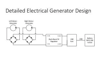
TSS installation Target buidling Klystron gallery (G02) Front end building DM cabinet Target utility block:Cabinet A;Cabinet B;Cabinet C. MCR:MCR Cabinet RFQ control cabinet;RFQ switchcabinet. ION control cabinet;ION switchcabinet. TSS #1:S-plc cabinet;G-plc cabinet.
115.4005 115.4001 115.4003 115.3067 D02.115.3064 G01.090.5005 MOp IONSwitchcabinetK02.U02 ION controlcabinetK01.U09 A-channelCabinetK01.U02 HEp WP 15 X t HEt HEf t X UPS&EPB ACC. UPS&EPB TE WHr G02.100.2001 RFQ SwitchcabinetK02.U01 RFQ controlcabinetK01.U08 XConv. WP 15 UPS&EPB ACC. D02.103.3064 MOp B-channelCabinetK01.U03 G02.100.1001 HEp WP 15 X t DMcabinetK01.U07 HEt HEf UPS&EPB ACC. t X TSS installation overview UPS&EPB TE D02.110.3016 WHr ICS MCRcabinetK01.U01 XConv. UPS&EPB DO2adm. D02.085.3064 D02.100.3016 MOp S-plccabinetK01.U05 C-channelCabinetK01.U04 HEp X t UPS&EPB DO2adm. HEt HEf t X UPS&EPB TE G-plccabinetK01.U06 WHr Fiber multimode XConv. UPS&EPB DO2adm. Fiber singelmode
TSS installation TSS cables overview: • Cables are Halogen Free Flame Retardant (HFFR) • Cables are shielded • Fibre cables:- Multi mode in relay train;- Single mode in plc train;- Single mode in gateway system. • Sensor cables FQAR-PG 1x2x0,5 non radiation area (analog signals) • Sensor cables Ölflex classic 110 CH non radiation area (digital signals) • Sensor cables JE-H(St)H radiation resistant 100 Mrad (analog signals)(radiation area)
TSS installation TSS layout example Fibre installation PLC gatewayfibremodule Fibrecables PLC trainfibremodule Fibreconnection box Relaytrainfibremodule
ESS-0015433 clause 9.3.1Electromagnetic compatibility (EMC) • Extract from ESS-0015433:- To reduce EMI measures have to be taken regarding EMC. • TSS design to resist EMI:EMC cabinets;Rittal VX25.Shieldedcables;Öflex 110 CH FQAR-PG 1x2x0,5JE-H(St)HFibrecables;FREEDM (Fibrecable)Shielded installation;Cable duct, OBO – SKSMU H85OBO Betterman – PR-S Rttal EMC cabinet
ESS-0015433 clause 12.2Enclosures • Extract from ESS-0015433:- Enclosures should be colored RAL 7035 (Grey).- Protection class IP54 is recommended for dry environment: • TSS Cabinet will use special colour. • TSS cabinets are protected to IP55 Cabinet
ESS-0015433 clause 12.5Ambient Thermal conditions TSS layout example • Extract from ESS-0015433:- Equipment shall be designed so that forced cooling is not needed unless otherwise is agreed with the ESS.- Faults in cooling or ventilation systems that may cause such a temperaturerise that it may damage to equipment shall result in an alarm • TSS cabinet internal temperature calculations result to no need of forced cooling. Calculated temperature level 32 degrees celcius is within TSS needs. • Temperatures above calculated level will be detected. Thermostat
ESS-0015433 clause 4.10.2Type of system earthing • Extract from ESS-0015433:- TN-S system with separate neutral conductor and protective conductor throughout the system, shall be used at ESS. • TSS use a TN-S system.
ESS-0015433 clause 4.10.5Uninterruptiblepowersupply, UPS • Extract from ESS-0015433:- Central UPS units shall primarily be used to facilitate service and maintenanceunless there are specific requirements for the electrical supply to a certain load. • TSS use centrally installed UPS with diesel backup.
ESS-0015433 clause 9.3.4Surge protection TSS layout example Supplycircuitsurge 22,5kA/4kV • Extract from ESS-0015433:- It might be necessary to install surge protection for sensitive equipment. Need of surge protection must be considered on case by case basis during the design. • TSS shall withstand a surge of 22,5kA/4kV present in supply cable. Components used such as PLC has a rated impulse withstandvoltage (Uimp) of 1kV.TSS design adapt to 22,5/4kV surge by use of a surge protectivedevice installed rated 25kA/0,9kV. Surgeprotectivedevice 25kA/0,9kV. Control equipmente.g. PLC, Uimp 1kV.
ESS-0015433 clause 8.3Short circuitbreakingcapacity TSS layout example • Extract from ESS-0015433: - The rated short circuit breaking capacity shall be at least equalto the prospective fault current at the point of installation. • TSS has a high rating to Short circuit breaking capacity of 50kA at point of installation. Low voltage switchgears are not yet designed and TSS adaptand secure design by using circuit breaker at supply circuitwith a high level of short circuit breaking capacity. Circuit breaker 50kA
ESS-0015433 clause 12.2Restricted access to instructed persons • Extract from ESS-0015433:- Means shall be provided to restrict access to live parts behinddoors to skilled or instructed persons. • Cabinets and controlswill be equippedwith ASSA lock system. • ASSA lock system aremanufacturedwithuniquekeys for TSS. Lockablehandle ASSA key ASSA cylinder
ESS-0015433 clause 2.3, 4.2, 4.8Selection of components • Extract from ESS-0015433:Clause 2.3: - Equipment, components and systems delivered to the ESS shall be CE-marked.Clause 4.2:- Standard components available in the ESS-0102876 ESS Approved Electrical StandardComponents shall primarily be used.Clause 4.8:- PVC materials (Polyvinyl Chloride) or other halogenated materials shall not be used. • TSS use CE-marked components. • TSS use ESS primarily use standard components. • TSS use Components without PVC.
ESS-0015433 clause 16.3.3Terminal blocks TSS layout example • Extract from ESS-0015433:- All cables shall be connected to knife switch terminals when so is possible. • TSS use terminals of disconnectable type. Disconnectable terminal
ESS-0015433 clause 15Labeling and marking • Extract from ESS-0015433:- Regarding general requirements for labelling and marking, see ESS-0094091 “ESS Rules for Marking and Labelling”.Extract from ESS-0094091:3.2.2 Labeling of components in racks/cabinets- The labeling shall still be present even if the component is replaced, which means that the labelis to be located in front or above the component and not attached to the component itself.A label carrier with printed labels attached is preferred. • TSS will use label carriers with printed labels attached.
ESS-0015433 clause 14.4Identification of conductors TSS layout example • Extract from ESS-0015433: • TSS follows ESS-rules to identification of conductors. • TSS also have an exception to ESS-rules by adding grey and brown colorfor identification of control circuits. By adding grey and brown color code, TSS are able to identify conductors belonging to all different systems.
ESS-0015433 clause 6.4Supply disconnecting device TSS layout example • Extract from ESS-0015433:- A supply disconnecting device shall be provided for each incoming source of supply. • The supplydisconnectingdevice is placedinside the cabinet, to avoidunathorizeddisconnectionof TSS. Supplydisconnectingdevice
ESS-0015433 clause 7.2.1 and 12.2protection against electric shock(Protection against direct contact) TSS layout example • Extract from ESS-0015433:clause 7.2.1 Protection by insulation of live parts- Live parts protected by insulation shall be completely covered with insulationthat can only be removed by destruction.clause 12.2 Enclosures- Where uninstructed people are not expected to have access IP2X shall be achieved. • TSS live parts areisolated • TSS components achieve IP20.
ESS-0015433 clause 7.3.2 and 9.4 protection against electric shock(Protection against indirect contact) TSS layout example • Extract from ESS-0015433:7.3.2 Protection by automatic disconnection of supply- Automatic disconnection of the supply of any circuit affected by an insulation fault is intended to prevent a hazardous situation resulting from a touch voltage.This protective measure comprises both:- Protective bonding of exposed conductive parts.- Overcurrent protective devices for the automatic disconnection of the supplyon detection of an insulation fault.Clause 9.4 Equipotentialprotective bonding- All extraneous conductive parts shall be connected to this system such as process and utility pipe systems, tanks, process units, metal structure of buildings, ventilation ducts, cable tray systems, control panels, MCC, distribution panels. • Exposedconductive parts areconnected to PE (protectiveearth) • TSS provideautomaticdisconnectionofsupply by circiutbreakers. • TSS control panels areconnected to Equipotentialprotective bonding (EPB)
ESS-0015433 clause 12.4 and 7.3.3protection against electric shocksocket outlet/disconnection of socket outlets TSS layout example • Extract from ESS-0015433:clause 12.4 Socket outlet- All electrical cabinets that have programmable units that needsa laptop terminal, e.g. to configure, shall be equipped with a socket outlet.clause 7.3.3 Disconnection of socket outlets- To protect persons, a RCD, maximum 30 mA, shall be connected to the wall socket outlet in the equipment. Local outlet placed inside cabinet (for PC use)is equippedwith a 30mA ResidualCurrentprotectiveDevice (RCD) RCD Socket
ESS-0015433 clause 8Protection of equipment TSS layout example • Extract from ESS-0015433:- Overcurrent protection shall be provided where the current in a circuit can exceed eitherthe rating of any component or the current carrying capacity of the conductors, whichever is the lesser value. TSS provideovercurrentprotection by circiutbreakers. Circuit breaker
ESS-0015433 clause 8 Protection of equipment TSS layout typical • Extract from ESS-0015433:8 Protectionofequipment8.1 Overcurrentprotection8.1.1 General- It is important to consider the availability aspect when designing the power distribution. It is important to oversee the structure of the power supply to ensure thatfaults in the system doesn ́t propagate and affect other parts of the system. • TSS adapt to rule also at the control circuits, by design that ensure that faults doesn’t propagate and affect other partsof the system. • However also of reasons such as: - to facilitatetroubleshooting;- to enableindividual alarms (insteadofsumalarms).
ESS-0015433 clause 10.1.2Control circuit supply TSS layout example • Extract from ESS-0015433:- Where control circuits are supplied from a DC power source, PELV 24 V DC shall be usedwhich is considered as the preferred control voltage within the ESS facility.All deviations from this principle shall be approved by ESS. • TSS use 24VDC power supplies. Power supply 24VDC
ESS-0015433 clause 10.1.4Protection against maloperation due to earth faults TSS layout example • Extract from ESS-0015433:- Earth faults in any control circuit shall not cause unintentional start or potentially hazardous movements or prevent the stopping of the machine.In order to fulfil this requirement, the neutral side (0 V) of the control circuit shall beconnected to the protective bonding circuit, earth. • TSS connect (-) side of control circuit to protective bonding circuit.
ESS-0015433 clause 10.1.324VDC Power Supply for PLC equipment TSS layout example • Extract from ESS-0015433:- 24VDC Power Supply for PLC equipment PLC and control equipment should be provideda separate 24VDC power supply that is separated from other 24VDC power suppliesused to power e.g. transducers, sensors, solenoid valves and other loadsconnected to the 24VDC power supply. • TSS adapt to rule by having separate 24VDC power suppliesto each system:PLC train; Relay Train;Gateway system.
ESS-0015433 clause 8.1.4Monitoring of circuits within control cabinets TSS layout example • Extract from ESS-0015433: • - Protection devices such as MCB ́s, electronic fuses and circuit breakersshall be provided with an auxiliary change over contact. Redundant power supplies shall be monitored individuallyto ensure that faults are detected. • TSS adapt to rule by monitoring of: Circuit breakers; 24VDC power supplies.TSS also monitor: Cabinet temperature; Cabinet door open; Relays; Control switches; Surge protective devises.
ESS-0015433 clause 11Operator interface and controldevices • Extract from ESS-0015433: - The actuators of hand operated control devices shall be selected and installedso that: - They are not less than 0,6 m above the servicing level and are within easy reach of the normal working position of the operator. • TSS adapt to rule. • The institute for Energy Technology (IFE), has beencontractedof ESSto provide the detailed design for the human factorsaspectsof the maincontrolroom (MCR).Mountingshall be:- not higherthan 1710mm and - not lowerthan 920mm. • TSS adapt to specificrequirements to suitableplacementsofcontrols.
ESS-0015433 clause 11Operator interface and controldevices • Extract from ESS-0015433:- Push buttons for start/on actuating must be designed and mountedso unintentional actuation is prevented. - Color of selector switches shall comply with table 4 otherwise they shall be in black.. • TSS adapt to rule by mountofprotectivecover to controldevices. • TSS adapt to ruleofcoloringofcontrols. Selector switch Protective cover switches Protective cover stop button Stop button
ESS-0015433 clause 11 and 11.1.2Operator interface and controldevices and Colourofindicatorlights • Extract from ESS-0015433:Clause 11 Operator interface and control devices - If indicator lights are used they should be of LED type to limit the need of service.Clause 11.1.2 Colour of indicator lights. • TSS indicatorlightsareof LED type. • TSS indicatorlightsarecolouredaccording to rule. - Indicating TSS ON by green- Indicating TSS OFF by yellow
ESS-0015433 clause 6.4.4Excepted circuits • Extract from ESS-0015433:Where a circuit is not disconnected by the supply disconnecting device following shall apply: - Permanent warning label shall be appropriately placed in proximity to thesupply disconnecting device.- A permanent warning label preferably with information added of the“source” circuit and location is affixed in proximity to each excepted circuit. • Warning label will be placed close to TSS supply disconnectingdevice. • Excepted circuits not disconnected of TSS supply disconnectingdevice will be marked. • It will be clearly stated of where to disconnect excepted circuitsnot disconnected of TSS supply disconnecting deviceto enable work to be carried out.
ESS-0015433 clause 12.2.2 Connections and routing TSS layout example • Extract from SS EN 60204-1 clause 11.2.2:- Control devices mounted in the same location and connected to thesupply voltage, or to both supply and control voltages, shall be grouped separately from those connected only to the control voltages. • TSS adapt to rule by dividing supply and power circuits fromcontrol circuits.
SS EN 60709 clause 4.2 Functional separation by physical separation TSS layout example • Extract from SS EN 60709: 4.2 Design errors- The potential for errors in the specifications of the requirementsfor the I&C systems important to safety cannot be ignored. Such design errors could lead to propagation of faults betweensystems, for example, insufficient insulation on cabling, inadequate sizing of conductors, etc. Means to address this typeof fault generally include conservative design of physical separation and electrical isolation. • TSS performphysical separation by:- separation ofcomponents to different systems;- separation ofconductors to different systems. Gateway system PLC train Relaytrain
SS EN 60709 clause 5.3.1 Functional separation by isolation TSS layout example • TSS extract signals from category A system componentsto systems with lower category according to SS EN 60709 clause 5.3.1. • TSS perform Isolation according to SS EN 60709 clause 5.3.2. • Extract from SS EN 60709:5.3 Isolation devices5.3.1 General- Where signals are extracted from category A system equipment and provided to systemsof a lower category, the transmission of these signals shall be through isolation devices that are included within the category A system. The isolation device shall be such that failures or conditions at their output terminals(which are connected to the lower category system) cannot prevent the safety actionof the category A system or sub-system to which the isolation device is connected. As an example, a circuit at category A may be monitored for alarms by a relay in that circuit at that category whose contacts provide alarms at a lower category. The electrical isolation provided shall meet the requirements of 5.3.2. Category A equipment Isolation methodtypical Cat A Cat Lower
SS EN 60709 clause 5.3.2 Functional separation by isolation TSS layout example • Extract from SS EN 60709:5.3.2 Isolation characteristicsFailures and conditions that shall be protected against includea) short-circuits between terminals or to ground;b) open circuits;c) application of the maximum a.c. or d.c. potential that could reasonably occur, consideringpotentials and sources available in both the category A and non-category A systems;d) electromagnetic and electrostatic interference.The properties of an isolation device shall include– tolerance of and isolation for the electrical surges and spikes defined in IEC 61000-6-5;– tolerance and isolation for EMI to IEC 61000-6-5;– simple barriers between close or adjacent terminals or contact groups on relay equipmentused for electrical isolation;– prevention of transmission of excessively high or damaging voltages.In this context, an assessment should be done of the maximum voltage that could beenvisaged under normal and faulted conditions, and its potential effects on the equipmentimportant to safety when applied to the isolation device terminals of the circuit of lesserimportance to safety.Precautions should also be taken to minimise the possibility that failure in a non-category Asystem causes spurious or premature actuation of a category A function.
E-plan documentation structureInformation of symbols and conductor color typical
E-plan documentation structureControl circuit diagram example
Thank you, any questions?