Download
1 / 11
110 likes | 199 Views
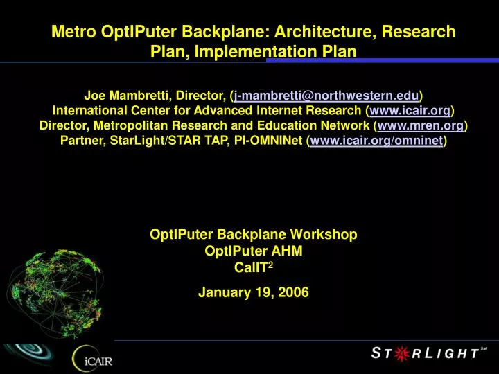
Metro OptIPuter Backplane: Architecture, Research Plan, Implementation Plan Joe Mambretti, Director, ( j-mambretti@northwestern.edu ) International Center for Advanced Internet Research ( www.icair.org ) Director, Metropolitan Research and Education Network ( www.mren.org )

E N D
Metro OptIPuter Backplane: Architecture, Research Plan, Implementation Plan Joe Mambretti, Director, (j-mambretti@northwestern.edu) International Center for Advanced Internet Research (www.icair.org) Director, Metropolitan Research and Education Network (www.mren.org) Partner, StarLight/STAR TAP, PI-OMNINet (www.icair.org/omninet) OptIPuter Backplane Workshop OptIPuter AHM CalIT2 January 19, 2006
Optical Control Plane Client Controller Client Layer Control Plane Optical Layer Control Plane UNI Controller Controller Controller Controller Controller I-UNI CI CI CI Client Device Client Layer Traffic Plane Optical Layer – Switched Traffic Plane
IEEE L2 Scaling Enhancements • Current Lack of Hierarchy • IEEE Developing Hierarchical Architecture • Network Partitioning (802.1q, vLAN tagging) • Multiple Spanning Trees (802.1s) • Segmentation (802.1ad, “Provider Bridges”) • Enables Subnets To be Characterized Differently Than Core • IETF – Architecture for Closer Integration With Ethernet • GMPLS As Uniform Control Plane • Generalized UNI for Subnets • Link State Routing In Control Plane • TTL Capability to Data Plane • Pseudo – Wire Capabilities
L1 10 Gbps • 10 GE Node Compute Clsuters • APIs • Automated Switch Panels • GMPLS • IETF GMPLS UNI (vs ONI UNI, Implications for Restoration Reliability) • 10 G Ports • MEMs Based • Services • Lightpaths with Attributes, Uni-directional, Bi-directional • Highly Secure Paths • OVPN • Optical Multicast • Protected Through Associated Groups • ITU-T SG Generic VPN Architecture (Y.1311), Service Requirements (Y.1312), L1 VPN Architecture (Y.1313)
HP-PPFS HP-APP2 HP-APP3 HP-APP4 VS VS VS VS Previously OGSA/OGSI, Soon OGSA/OASIS WSRF tcp • Lambda Routing: • Topology discovery, DB of physical links • Create new path, optimize path selection • Traffic engineering • Constraint-based routing • O-UNI interworking and control integration • Path selection, protection/restoration tool - GMPLS tcp ODIN Server Creates/Deletes LPs, Status Inquiry Access Policy (AAA) Process Registration GMPLS Tools LP Signaling for I-NNI Attribute Designation, eg Uni, Bi directional LP Labeling Link Group designations System Manager Discovery Config Communicate Interlink Stop/Start Module Resource Balance Interface Adjustments Process Instantiation Monitoring Discovery/Resource Manager, Incl Link Groups Addresses OSM ConfDB UNI-N Physical Processing Monitoring and Adjustment Data Plane Resource Resource Resource Resource Control Channel monitoring, physical fault detection, isolation, adjustment, connection validation etc
Simple Path Control Protocol Specification IETF Draft by D. Lillethun, J. Lange, J. Weinberger (iCAIR) (Ref:www.ietf.org) • “The Simple Path Control Protocol (SPC) defined in this document is a new protocol defined to enable processes external to networks to establish, delete and monitor paths, including lightpaths. The architecture of this protocol establishes a method of providing messages, and procedures that allow such external processes to directly request network resources related to path provisioning.” • “Various methods exist that allow paths, including lightpaths, to be established within a network. The Simple Path Control Protocol was developed to enable external processes, including applications, to communicate messages that allow for such paths to be created, deleted and monitored. SPC defines a message that can be sent to a server that is capable of establishing a path on lower-layer network elements. After receiving such a request, the server is responsible for identifying the appropriate path through the controlled network topology and configuring it to fulfill the request. SPC also provides facilities for explicitly releasing a path when it is no longer needed, and for simple query facilities about the current network state.” http://www.icair.org/spc/spc-internet-draft_august2004.html
Optera 5200 OFA 1310 nm 10 GbE WAN PHY interfaces 5200 OFA l l 1 1 l l 2 2 l l 3 3 Optera 5200 10Gb/s TSPR Optera 5200 10Gb/s TSPR Optera 5200 10Gb/s TSPR l l 4 4 Fiber 5200 OFA StarLight Interconnect with other research networks 5200 OFA Fiber in use Fiber not in use OMNInet Network Configuration 2006 • 8x8x8l Scalable photonic switch • Trunk side – 10 G WDM • OFA on all trunks 750 North Lake Shore W Taylor DOT Clusters Photonic 10 GE l 10 GE Photonic 1 PP PP 10/100/ GIGE Node 10 GE l 10 GE Node 2 NWUEN-1 8600 8600 Optera 5200 10Gb/s TSPR 10/100/ GIGE l 3 l 4 Optera Metro 5200 OFA NWUEN-5 INITIAL CONFIG: 10 LAMBDAS (ALL GIGE) CAMPUS FIBER (16) … CAMPUS FIBER (4) NWUEN-6 NWUEN-2 NWUEN-3 EVL/UIC OM5200 710 Lake Shore TECH/NU-E OM5200 10 GE l PP 1 Photonic 10/100/ GIGE 10 GE l INITIAL CONFIG: 10 LAMBDA (all GIGE) 8600 2 Node CAMPUS FIBER (4) l 3 l 4 LAC/UIC OM5200 NWUEN-8 NWUEN-9 NWUEN-7 NWUEN-4 600 S. Federal 10GE LAN PHY (Dec 03) 10 GE PP Photonic 10 GE 8600 To Ca*Net 4 Node 10/100/ GIGE
Default configuration: Tribs can be moved as needed Could have 2 facing L2 SW Only TFEC link can support OC-192c (10G Wan) operation Non -TFEC link used to transport Ge traffic 600 N. Federal Optical Switch Optical Switch 1890 W. Taylor 1x 10G Wan 1 x 10G Wan High Performance L2 Switch High Performance L2 Switch Ge (x2) Ge (x2) Optical Switch Optical Switch 1 x 10G Wan 1 x 10G Wan High Performance L2 Switch High Performance L2 Switch Ge (x2) Ge (x2) 710 North Lake Shore Drive 750 North Lake Shore Drive Trib Content OC-192 – with TFEC 16 OC-192 – without TFEC 12 Ge 8 OC-48 0 Non - TFEC Link TFEC = Out of band error correction TFEC Link OMNInet 2005
Sheridan, Evanston Core Testbed Site Fiber 350 E. Chicago 710 North Lake Shore Drive Core Node 111 North Canal 600 South Federal 1940 West Taylor
The OptIPuter LambdaGrid UIC UoA Seattle Northwestern Chicago Amsterdam StarLight CERN NASA Ames CENIC LA GigaPOP NASA JPL NASA Goddard ISI UCSD UCI San Diego CENIC San Diego GigaPOP