Download
1 / 38
390 likes | 733 Views
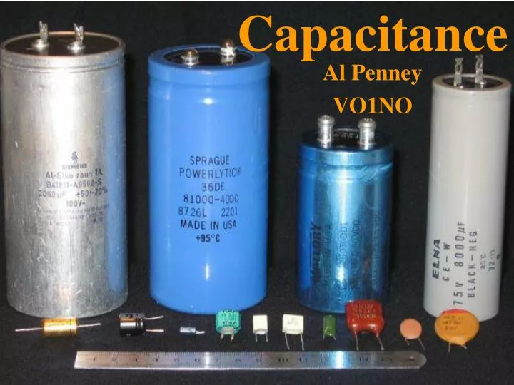
Capacitance. Al Penney VO1NO. Capacitance. Capacitance is the property of an electrical circuit that opposes a change in voltage . When a voltage applied across a circuit is increased or decreased, capacitance resists that change. Construction of a Capacitor.

E N D
Capacitance Al Penney VO1NO
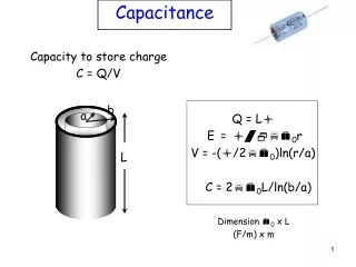
Capacitance • Capacitance is the property of an electrical circuit that opposes a change in voltage. • When a voltage applied across a circuit is increased or decreased,capacitance resists that change.
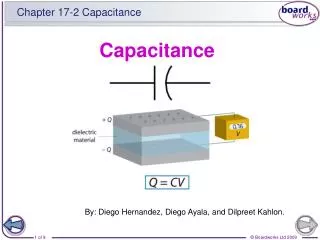
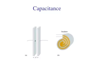
Construction of a Capacitor • A basic capacitor consists of 2 conducting metallic plates separated by a layer of air or other insulating material such as glass, mica or even oil. • The insulating material is called the Dielectric.
Axial Lead Capacitor Metal Foil Dielectric Film
A similar capacitor at Marconi’s station in Clifden, Ireland. Note the size of the two men!
Capacitors in a DC Circuit - - - - + + + +
Capacitors in a DC Circuit • When first connected to a battery, electrons flow from the negative battery terminal to the capacitor plate and remain there because the dielectric prevents them from travelling to the opposite plate. • Electrons on the opposite plate are attracted to the positive battery terminal. • Eventually, the capacitor reaches the same voltage as the battery, and no more electrons flow. • The capacitor is then said to be Charged. • Capacitors block the flow of DC.
Capacitors in an AC Circuit • Current cannot pass through a capacitor but Alternating Current appears to. • If the voltage across the plates of the capacitor is continuously varied, the number of electrons varies. • As the voltage changes then, it appears as though a current is flowing even though electrons do not actually traverse the dielectric.
Electrons • Individual electrons are too small to have an effect in everyday electronics, so we use a larger number of them to make practical measurements. • The Coulomb is equal to 6.3 x 10¹⁸ electrons (6,300,000,000,000,000,000 electrons). • For example, one Ampere = 1 Coulomb per Second.
The Farad • The unit of measure for capacitance is the Farad. • One Farad is the capacitance in which a charge of 1 Coulomb produces a difference of 1 Volt between the plates. • One Farad is much too large a value for practical circuits however.
Practical Capacitor Units • Practical capacitors are measured in: • Microfarads, or millionths of a Farad. They are abbreviated as μf, and equal to 1 x 10⁻⁶ Farads. The old abbreviation was mfd. • Picofarads, or millionth millionths of Farads, are equal to 1 x 10-12 Farads. They are abbreviated as pf. They were originally called Micromicrofarads, and you may still encounter the abbreviation mmf.
Factors Affecting Capacitance • Plate Area: The larger the plate area, the greater the capacitance. • Distance Between the Plates: The closer together the plates, the greater the capacitance. Of course, it is necessary to prevent the charge from jumping the gap (arcing). • Changing the Dielectric:Greater capacitance can be obtained by using a dielectricother than air. Glass, mica, oil and mylar are some of the materials that have a greater Dielectric Constant than air. This is because they permit the plates to be closer together, and because they have electrons that can move slightly.
Capacitors in Parallel • Capacitors in Paralleladd their values. • This is because it is equivalent to a single capacitor with a greater surface area. CT= C1 + C2 + C3
Example of Capacitors in Parallel 75 μf CT = C1 + C2 + C3 50 μf CT = 75μf + 50μf + 75μf CT = 200μf 75 μf
Capacitors in Series • Capacitors in Series must be treated the same way that resistors and inductors in parallel are treated. CT
Example of Capacitors in Series CT = 1 . 1 + 1 + 1 C1 C2 C3 CT = 1 . 1 + 1 + 1 50 75 25 CT = 1 . 3 + 2 + 6 150 150 150 CT = 1 = 150/11μf = 13.64μf 11 150 50 μf 75 μf 25 μf
Working Voltage • All capacitors have a characteristic working voltage, sometimes called the voltage rating. • It is the maximum DC voltage that the capacitor can sustain continuously without excessive leakage or breaking down – ie: having the charge jump from one plate to the other (arc). • Arcing will destroy most capacitors. Electrolytics can self-heal after small arcs. Even air-gap variable capacitors can be damaged by arcing.
Surge Voltage • Surge voltage is the maximum voltage that can be withstood for a few seconds after the start-up of a circuit. • It was an important parameter for tube circuits, but is not very relevant for modern solid-state circuits.
Reactance • Reactance is the opposition to the flow of Alternating Current (AC). • Reactance has no effect on the flow of Direct Current (DC).
Capacitive Reactance • Capacitive Reactance is the opposition to the flow of AC by capacitance. • As the frequency of the AC increases, Capacitive Reactance decreases. • The Symbol for Capacitive Reactance is XC. • XC is expressed in ohms. • Even though it is expressed in ohms, power is not dissipated by Reactance! Energy stored in a capacitor during one part of the AC cycle is simply returned to the circuit during the next part of the cycle!
Energy Storage and Release Energy Released Energy Stored
Capacitive Reactance • Where: F = frequency in Hertz C = capacitance in Farads π = 3.14
Capacitive Reactance However, Farads and Hertz are cumbersome units, so we can use other units: F = frequency in Megahertz (MHz) C = capacitance in Microfarads (μf) π = 3.14
Capacitive Reactance Example 1 • What is the capacitive reactance of a 470 pf capacitor at a frequency of 7.15 MHz? • Remember that 470 pf = 0.000470 μf.
Capacitive Reactance Example 2 • What is the capacitive reactance of that same 470 pf capacitor at a frequency of 14.29 MHz? • Again, remember that 470 pf = 0.000470 μf.
Capacitive Reactance Examples • Note that as the frequency increased from 7.15 MHz to 14.290 MHz, the Capacitive Reactance decreased from 47.4 ohms to 23.7 ohms. • Remember: • Capacitors block DC; • Capacitors store energy as an electrical charge; and • As the frequency increases,capacitive reactance decreases (and vice versa!).