Download
1 / 13
140 likes | 176 Views
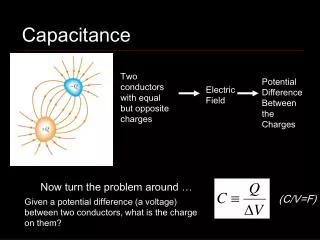
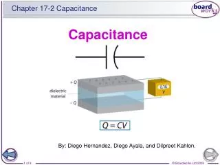
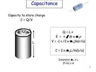
Capacitance. Chapter 26 (Continued). Capacitors. Q. -Q. If the plates are held at an electric potential difference V then get charges Q and -Q on the plates with Q=CV. -. +. V. V should be really be written ∆V, but we often don’t bother.

E N D
Capacitance Chapter 26 (Continued)
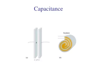
Capacitors Q -Q If the plates are held at an electric potential difference V then get charges Q and -Q on the plates with Q=CV - + V V should be really be written ∆V, but we often don’t bother. The battery’s ability to push charge is called its “electromotive force” or emf. A 6V battery has an emf of 6V. We often refer to electric potential, potential difference, and emf simply and sloppily as “voltage,” because all have units of volts.
- + - + - + - + +Q -Q - + - + - + - + - + - + - + - + - + - + - + - + Dielectrics in Capacitors • Suppose we fill the space between the plates of a capacitor with an insulating material (a “dielectric”): • The material will be “polarized” - charge -e electrons are pulled to the left, stretched away from the positively charged atomic cores. • Consequently the E field within the capacitor will be reduced.
- + - + - + - + +Q -Q - + - + - + - + - + - + - + - + - + - + - + - + Dielectrics in Capacitors • At a point in the interior some electrons shift left. But other electrons shift over to replace them (on average). So there is no net charge density in the bulk. • However, some electrons are pushed towards the left plate, and there is a deficit of electrons at the right plate. • Hence there is some induced charge -Q’ at the very left side of the insulator, and an induced charge +Q’ at the very right side.
Dielectrics in Capacitors + + + + - - - - - - - - - - - - - +Q -Q + + + + + + + + + +Q’ -Q’ It turns out that Q’ is proportional to Q. It is convenient to write the constant of proportionality this way: k is called the dielectric constant. Its value depends on the dielectric (whether it is plastic, glass, etc.) For a vacuum k=1; for air k is close to 1. Except for a vacuum k >1.
Dielectrics in Capacitors + + + + - - - - - - - - - - - - - +Q -Q + + + + + + + + + +Q’ -Q’ Gaussian Surface (a 3D box) • Suppose the field inside is E0 without the dielectric. Let us calculate the new field E when the dielectric is present. • Use Gauss’s Law in both cases: • E0 = Q / (0 A) and E = (Q – Q’) / (0 A) • E0 / E = Q / (Q – Q’) E0 / E = or E = E0/k • Thus the field is reduced by factor k
Dielectrics in Capacitors • We see that a dielectric reduces the electric field by a factork (E=E0/) • Hence for a given charge Q on the metal plate the potential difference V = Ed is also reduced by k (V=V0/k). • Thus C= Q/V is increased by k[C=C0 where C0=Q/V0 is the capacitance without the dielectric]. • parallel plate capacitor • with dielectric. • Adding a dielectricincreases the capacitance.
Dielectrics & Gauss’s Law With a dielectric present, Gauss’s Law can be rewritten from +q -q’ to Instead of having to think about the confusing induced charge q’, we can simply use the free charge q. But E is replaced by kE.
Parallel and Series Series Parallel
Capacitors in Circuits (Symbol for a capacitor) +Q -Q C V A piece of metal in equilibrium has a constant value of potential. Thus, the potential of a plate and attached wire is the same. The potential difference between the ends of the wires is V, the same as the potential difference between the plates.
Capacitors in Parallel C1 q1 • Suppose there is a potential • difference V between a and b. • Then q1=C1V & q2=C2V a b q2 C2 • We want to replace C1 and C2 with an • equivalent capacitance for which q=CV, • where the charge on C is q = q1 + q2 • From the above, q=q1 + q2=(C1 + C2)V. That is, q=CV with V b a C - q C = C1 + C2 • This is the equation for capacitors inparallel. • Increasing the number of capacitors increases the capacitance.
Capacitors in Series C1 C2 C a -q +q -q +q b a -q +q b V1 V2 V • The capacitors have the same q but different potential differences. Here the total potential difference between a and b is V = V1 + V2 • Again we want to find q=CV with C an equivalent capacitance. • Use V1 = q/C1 and V2 = q/C2 • Then V = V1 + V2 = q /C1 +q /C2 = [(1/C1) + (1/C2)]q • or, V = q/C with 1 / C = 1 / C1 + 1 / C2 • This is the equation for capacitors in series. • Increasing the number of capacitors decreases the capacitance.
Equivalent Capacitors Parallel Series For each there is an equivalent single capacitor C for which q=CV. Here q is the total charge to flow down the main wire, and V the potential difference across the unit. C1 C1 C2 C2 C = C1 + C2 1 / C = 1 / C1 + 1 / C2