Download
1 / 30
420 likes | 724 Views
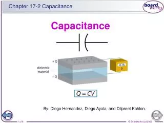
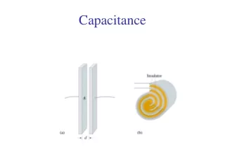
Capacitance. AP Physics B. Capacitors. Consider two separated conductors, like two parallel plates, with external leads to attach to other circuit elements. Such a device is called a capacitor.

E N D
Capacitance AP Physics B
Capacitors Consider two separated conductors, like two parallel plates, with external leads to attach to other circuit elements. Such a device is called a capacitor. There is a limit to the amount of charge that a conductor can hold without leaking to the air. There is a certain capacity for holding charge.
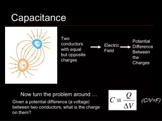
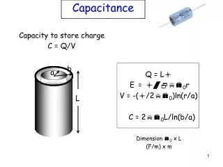
Capacitance The capacitance (C) of a conductor is defined as the ratio of the charge (Q) on the conductor to the potential (V) produced. Capacitance:
Capacitance in Farads One farad (F) is the capacitance C of a conductor that holds one coulomb of charge for each volt of potential. Example:When 40 mC of charge are placed on a con- ductor, the potential is 8 V. What is the capacitance? C = 5mF
For these two parallel plates: Area A +Q d -Q Parallel Plate Capacitance You will recall from Gauss’ law that E is also: Qis charge on either plate. Ais area of plate. And
A 0.4 m2 d 3 mm Example 2.The plates of a parallel plate capacitor have an area of 0.4 m2 and are 3 mm apart in air. What is the capacitance? C = 1.18 nF
Changing Area + + + + + - + - + - A - - Changing d - - Variable Capacitor d Microphone Applications of Capacitors A microphone converts sound waves into an electrical signal (varying voltage) by changing d. The tuner in a radio is a variable capacitor. The changing area A alters capacitance until desired signal is obtained.
Energy of Charged Capacitor The potential energyU of a charged capacitor is equal to the work (qV) required to charge the capacitor. If we consider the average potential difference from 0 to Vf to be V/2: Work = Q(V/2) = ½QV
Capacitor of Example 3. C = 11.1 nF 200 V U = ? Q = 2.22 mC Example 3: In a capacitor, we found its capacitance to be 11.1 nF, the voltage 200 V, and the charge 2.22 mC. Find the potential energy U. U = 222 mJ Verify your answer from the other formulas for P.E.
Ground Battery Capacitor + - + - + - + - - + - + - + - Electrical Circuit Symbols Electrical circuits often contain two or more capacitors grouped together and attached to an energy source, such as a battery. The following symbols are often used:
+ - + - + - + - + - + - C1 C3 C2 Battery Capacitors in Series Capacitors or other devices connected along a single path are said to be connected in series. See circuit below: Series connection of capacitors. “+ to – to + …” Charge inside dots is induced.
Q2 Q3 Q1 Charge is same: series connection of capacitors. + - + - + - + - + - + - C1 C3 C2 Battery Q = Q1 = Q2 =Q3 Charge on Capacitors in Series Since inside charge is only induced, the charge on each capacitor is the same.
V2 V3 V1 Total voltage V Series connection Sum of voltages + - + - + - + - + - + - C1 C3 C2 • • Battery A B V = V1 + V2 + V3 Voltage on Capacitors in Series Since the potential difference between points A and B is independent of path, the battery voltage V must equal the sum of the voltages across each capacitor.
V1 V2 V3 + - + - + - + - + - + - C1 C2 C3 Q1= Q2 = Q3 Equivalent Capacitance: Series V = V1 + V2 + V3 Equivalent Ce for capacitors in series:
C1 C2 C3 2 mF 4 mF 6 mF + - + - + - 24 V + - + - + - Example 1.Find the equivalent capacitance of the three capacitors connected in series with a 24-V battery. Cefor series: Ce = 1.09 mF
Ce C1 C2 C3 1.09 mF 2 mF 6 mF 4 mF 24 V + - + - + Ce = 1.09 mF - 24 V + - + - + - Example 1 (Cont.):The equivalent circuit can be shown as follows with single Ce. Note that the equivalent capacitance Cefor capacitors in series is always less than the least in the circuit. (1.09 mF < 2 mF)
Ce C1 C2 C3 1.09 mF 2 mF 6 mF 4 mF 24 V + - + - + - 24 V + - + - + - Example 1 (Cont.):What is the total charge and the charge on each capacitor? Ce = 1.09 mF QT= 26.2 mC QT = CeV = (1.09 mF)(24 V); For series circuits: QT = Q1 = Q2 = Q3 Q1 = Q2 = Q3 = 26.2mC
C1 C2 C3 2 mF 6 mF 4 mF 24 V + - + - + - + - + - + - Example 1 (Cont.):What is the voltage across each capacitor? VT= 24 V Note: VT = 13.1 V + 6.55 V + 4.37 V = 24.0 V
Example: C1 C2 + - + - + - + - 3 mF 6 mF Short Cut: Two Series Capacitors The equivalent capacitance Ce for two series capacitors is the product divided by the sum. Ce = 2 mF
Parallel capacitors: “+ to +; - to -” Voltages: VT = V1 = V2 = V3 C1 C2 C3 + + + + + + - - - - - - Parallel Circuits Capacitors which are all connected to the same source of potential are said to be connected in parallel. See below: Charges: QT = Q1 + Q2 + Q3
Parallel capacitors in Parallel: C1 C2 C3 + + + + + + - - - - - - Equivalent Capacitance: Parallel Q = Q1 + Q2 + Q3 Equal Voltages: CV= C1V1 + C2V2 + C3V3 Equivalent Ce for capacitors in parallel: Ce = C1 + C2 + C3
C3 C2 24 V C1 2 mF 4 mF 6 mF VT = V1 = V2 = V3 Q = Q1 + Q2 + Q3 Example 2.Find the equivalent capacitance of the three capacitors connected in parallel with a 24-V battery. Cefor parallel: Ce = (2 + 4 + 6) mF Ce = 12 mF Note that the equivalent capacitance Cefor capacitors in parallel is always greater than the largest in the circuit. (12 mF > 6 mF)
Q = Q1 + Q2 + Q3 C3 C2 24 V C1 2 mF 4 mF 6 mF Example 2 (Cont.)Find the totalcharge QTand charge across each capacitor. Ce = 12 mF V1 = V2 = V3 = 24 V QT = CeV Q1 = (2 mF)(24 V) = 48 mC QT= (12 mF)(24 V) Q1 = (4 mF)(24 V) = 96 mC QT = 288 mC Q1 = (6 mF)(24 V) = 144 mC
24 V C1 C2 3 mF 4 mF C3 6 mF 24 V C1 24 V C3,6 2 mF Ce 6 mF 4 mF Example 3. Find the equivalent capacitance of the circuit drawn below. Ce = 4 mF + 2 mF Ce = 6 mF
24 V C1 C2 3 mF 4 mF C3 6 mF 24 V C1 24 V C3,6 2 mF Ce 6 mF 4 mF Example 3 (Cont.)Find the total charge QT. Ce = 6 mF Q = CV = (6 mF)(24 V) QT = 144 mC
24 V C1 C2 3 mF 4 mF C3 6 mF Example 3 (Cont.)Find the charge Q4and voltage V4across the the 4-mF capacitor. V4 = VT = 24 V Q4 = (4 mF)(24 V) Q4 = 96 mC The remainder of the charge: (144 mC – 96 mC) is on EACH of the other capacitors. (Series) This can also be found from Q = C3,6V3,6 = (2 mF)(24 V) Q3 = Q6 = 48 mC
24 V C1 C2 3 mF 4 mF C3 6 mF Example 3 (Cont.)Find the voltages across the 3 and 6-mF capacitors. Q3 = Q6 = 48mC Note: V3 + V6 = 16.0 V + 8.00 V = 24 V Use these techniques to find voltage and capacitance across each capacitor in a circuit.
Summary: Series Circuits Q = Q1 = Q2 = Q3 V = V1 + V2 + V3 For two capacitors at a time:
Summary: Parallel Circuits Q = Q1 + Q2 + Q3 V = V1 = V2 =V3 For complex circuits, reduce the circuit in steps using the rules for both series and parallel connections until you are able to solve problem.
AP Physics HW 3/26 • Read Chapter 16.3 and 16.5 (that’s it!) • Do Problems…#63, 65, 67, 69, 71, 93, 95 • Finish ALL other HW problems sets • Yosemite $ DUE. • T-Shirt Design? ...25 points up for grabs!