Download
1 / 28
300 likes | 516 Views
Studies of proton generation and focusing for fast ignition applications Fast Ignition Workshop Nov 4th 2006. Andrew Mackinnon Lawrence Livermore National Laboratory.

E N D
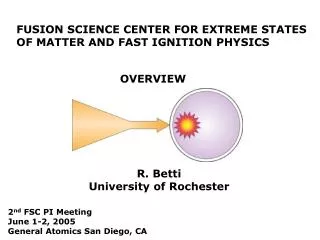
Studies of proton generation and focusing for fast ignition applications Fast Ignition Workshop Nov 4th 2006 Andrew Mackinnon Lawrence Livermore National Laboratory This work was performed under the auspices of the U.S. Department of Energy by University of California Lawrence Livermore National Laboratory under contract No. W-7405-Eng-48.
Co-authors and acknowledgements K. Akli, F. Beg, M.H. Chen, H-K Chung, M Foord, K. Fournier, R.R. Freeman, J. S. Green, P. Gu, J. Gregori, H. Habara, S.P. Hatchett, D. Hey, J.M. Hill J.A. King, M.H. Key, R. Kodama, J.A. Koch, M Koenig, S. Le Pape, K. Lancaster, B.F.Lasinski, B. Langdon, S.J. Moon, C.D. Murphy,, P.A. Norreys, N. Patel, P.K Patel, H_S.Park, J. Pasley , R.A. Snavely, R.B. Stephens, C Stoeckl, M Tabak, W. Theobold, K. Tanaka, R.P. Town, S.C. Wilks, T. Yabuuchi,B Zhang, • This work is from a US Fusion Energy Program Concept Exploration collaboration between LLNL, General Atomics, UC Davis, Ohio State and UCSD • International collaborations at RAL,LULI and ILE have enabled most of the experiments • Synergy with an LLNL ‘Short Pulse’ S&T Initiative has helped the work • US collaboration in FI has recently expanded in a new Fusion Science Centre • linking 6 Universities and GA with LLNL and LLE and a new Advanced Concept Exploration project between LLNL,LLE,GA, UC Davis , Ohio State and UCSD
The power and flux requirements for proton fast ignition are similar to the original electron scheme 1mm • Proton-FI (1) requirements: heat 300 g/cc with 18 kJ protons at 3 MeV in 10 ps over 30-40 m dia. (R~2.5 g/cm2) • Proton foil to fuel distance, interaction with plasma (~ 1 mm) • Requires ~180 kJ laser energyif laser conversion into protons = 10% • Requires proton spot size 30-40 m (by focusing) Protons Laser Imploded Fuel • Outstanding questions: • Can laser conversion efficiency be increased from 10% to 15-20%? • Can sheath uniformity be improved to give 30-40m spot with 1mm spherical focusing target? * For work on improving electron coupling, see B. Lasinski, K.Tanaka (1)) Roth et al.,86,436 PRL 2000, Atzeni et al., 2002; Temporal et al., PoP 9,3102 (2002)
Laser driven proton beams: Extreme hot electron pressure,nhTh , drives sheath ion acceleration mechanism • Target: 15µm Au • N = 1.4 E12 protons • T = 3.0 MeV • E = 670 mJ • = 2% laser energy Divergence 1-20deg e- 3.8MeV 6.5MeV 11MeV 14MeV 17MeV 20MeV • At relativistic laser intensities, Lorenz force accelerates electrons in forward direction • Escaping MeV electrons set up Debye Sheath • Trapped electrons reflux through target transferring energy to ions and thermal plasma • Sheath field accelerates protons from contaminant layers on target surface Eacc ~ TH/d = TH /(TH / nH)1/2 Eacc ~ (nH TH)1/2 ~ MeV/m MeV electron e- Proton beam RCF film Laser Debye Sheath Proton beam from Titan laser E= 37J 0.7ps 5x10¹⁹Wcm-2
Emax vs laser pulselength Titan data Peak Proton Energy, Ep (MeV) Ep (I)0.5 scaling Laser pulselength (ps) Titan data shows good proton beam at p = 10ps and strong dependence on target thickness Titan Emax vs target thickness 1x10²⁰ Wcm-2 Titan data 5x10¹⁸ Wcm-2 Peak Proton Energy, Ep (MeV) Best fit to data Target thickness (m) • Good proton beam obtained at 10ps (but intensity reduced to 5x10¹⁸ Wcm-2) • If proton beam scales as Emax(I)0.5then @10ps Emax~ 40MeV at 1x10²⁰Wcm-2 • Rapid decrease in peak proton energy vs target thickness (L)-0.4
Maximum conversion efficiency obtained to date is 10% using PW class systems from CH targets = 10% : Nova (1999), 500J, 0.5ps, 55m CH Efficiency > 3MeV % = 2% : Titan (2006), 35J, 0.7ps, 15m Au Energy J / thickness micron
Hybrid PIC simulations (LSP1) are being used to study methods to optimize proton conversion efficiency and focusing LSP Electrons injected at front of target LSP proton cut off vs target thickness I = 1x10¹⁹ Wcm-2 M Foord et al. • LSP: Hot electrons injected with appropriate kThot (ponderomtive or “Beg”) scaling with laser intensity • LSP shows decrease in conversion efficiency (& max proton energy ) with increasing target thickness as experimentally observed 1D. R. Welch, et al, Nucl. Inst. Meth. Phys. Res. A 242, 134 (2001).
LSP has reproduced the essential features from JanUSP (Callisto) laser: 10J, 100fs, 1x10²⁰ Wcm-2 Proton spectrum LSP vs JanUSP Radial distribution proton acceleration from 5µm Au foil Ep = 1.7MeV R (µm) Data Z (µm) Emax • 10J, 100fs, 1x10²⁰Wcm-2 interaction with 5m gold with 12Å layer of CH • 2D LSP: 0.5J electrons injected kThot = Edrift = 0.9MeV Maxwellian • LSP Matches experimentally observed proton flux, Emax (cut off) and Ep
LSP show proton conversion can be improved using low Z substrates and using hydrogen rich targets 5m Al substrate 5m Au substrate 0.1m CHO layer 0.1m CH4 layer Electrons Electrons kThot = 2.5MeV kThot = 0.9MeV 50% Refluxing hot e H+ Fraction of Injected Energy Hot e C+6 Thermal e Al+4 6% • Reduce Thermal energy ( use Low Z substrate, Al instead of Au) • Increase hot electron pressure: increase kThot • Use CH4 instead of CH • Cryogenic hydrogen should provide highest conversion efficiency
Solid CH4 and H2 targets could be tested using cryo target cell ~7MeV “LULI show no beam degradation up to 100 nm CH coating at the rear of Au foils” M. Roth et al., (PRST-AB, 5, 061301 (2002)) • Solid Methane target cell CH4 or H2 50mm SPEC Laser • Layer uniformity and thickness monitor 5m Gold substrate 100nm CH4 layer
Metal hydrides could present a simpler solution than cryogenic methane or hydrogen layers • Hydrogen density in hydride can be higher than liquid H2
1D simulations predict that the atomic weight of hydride appears to be an important factor in efficiency Fraction of energy in H+ Hot electron to proton conversion eff (%) Fraction of energy in heavy ion Current experiments with contaminant layers • Heavy ions are left behind at back surface during ion separation
LSP simulations predict that Erbium and Uranium hydride have high electron to proton conversion efficiency • Assumed 1000 Å layer of Mg+10, Er+10, U+10 on 5 m Au foil. • Hot electron temperature, kThot = Edrift= 880 keV • Heavy ions are left behind at back surface during ion separation.
ErH2 and ErH3 • Films 100nm thick have been manufactured by reactive sputtering* • Oxide and hydrogen barriers may be necessary to maximize hydrogen content 10-15 umgold layer * Sandia National lab Laser ~1 um Eror U layer • Surface contaminants and barrier layers will be removed by ion sputtering** 10-30 nm Pd oxidationprotective layer ** M. Allen, P. K. Patel, et al., PRL 93 265004 (2004) Erbium Hydride has practical advantages for near term proton efficiency studies It is not Uranium!
Proton focusing appears promising - but scaling studies are required • Hemisphere focuses protons to < 50m spot • Planar foil Te = 4eV, Hemisphere heating, Te = 20eV • Emittance allows for much smaller spot (< 1m) • Problem is mapping of divergent flow onto hemisphere • Improvements required in sheath toplogy • Simplest solution - increase laser spot size P. Patel et al., PRL 91 125004 (2003)
320 mm Al shell Protons X-ray phc image High intensity on small focal region causes bell shaped sheath with complex laminar flow and ‘aberrated’ focus X-ray phc image Gekko PW data Laser Proton heating PW laser Cu Ka image Cu Ka image Sheath • Divergence of electrons from small laser spot leads to non uniform sheath • Analogous to spherical aberration • Protons focus in different planes along hemisphere axis • Best focus not at geometric center of hemisphere D/R ≠ 1 Cu Ka image X- Best focus D Laser R 20mm heated spot
Increasing laser spot size is a simple way of reducing proton spot size .88 ps .88 ps 1.2 ps 1.6 ps 1.2 ps H H H H H 10 mm-dia 1J, 100 fs laser pulse 50 mm-dia 1J, 100 fs laser pulse
Z=70 mm (best focus) Z=80 mm Z=90 mm Z=60 mm Z=50 mm Improved sheath planarity reduces proton spot and depth of focus 10 um spot 50 um spot Z=60 mm Z=70 mm Z=80 mm (best focus) Z=50 mm Z=90 mm • Proton radial focusing for 3MeV proton energy • Best focus is at 1.4-1.6 x hemisphere radius (D/R = 1.4 - 1.6) • Larger spot improves focusing from 5 m to 2.5 m diameter • Self similar scaling for 50 m spot would give proton focus of 25 m for 1000m Hemisphere
A new mesh imaging technique is being developed to investigate proton focusing Laser view R Fine mesh w/ element separation = 25m Laser : spot~50µm Focal Plane RCF pack for measuring proton dose x hemisphere mesh Side view D mesh d = 250m 1mm 70mm Oblique view XUV Imagers at 68 and 256eV to measure size of heated region Laser View of xuv Shot No:060622_s1: 20µm thick, 350µm Diameter Al hemi-shell with 25µmx25µm Cu mesh at 1mm spacing This technique allows simultaneous determination of location of proton focus,D, size of proton spot and extent of heated region
Proton heated spot correlates well with RCF image of proton beam 68eV XUV image RCF at 20MeV 600µm Titan laser pulse 400µm 400µm Proton beam 350µm diameter hemisphere 1000lpi mesh • 68eV XUV image showing plasma emission from mesh heated by focused proton beam • RCF shows same spot size as XUV image • Measured mesh magnification gives location of proton focus D/R~1.9
25m Strong heating was observed with mesh placed close to geometric focus 68eV XUV 256eV XUV • Mesh at +50m from geometric focus • 68eV image consistent with high Temperature • RCF image @ 20MeV agrees well with ~ 30m diam 256eV image • Brightness consistent with 100-200eV plasma • Proton source d/R ~1.8 Titan Laser Proton dose (20MeV) 25m
Conclusions • Proton fast ignition is an attractive alternative to electron ignition • Required proton temperature can be achieved for available laser irradiance - but need higher proton energy density • Conversion efficiency: Require 15-25% > 3MeV • Maximize hot electron production • Determine optimum pre-pulse level for electron production + proton conversion • Maximize energy into protons - CH4, H or hydride targets • Proton focus: • Require 30-40m spot with 1000m radius spherical target • Understand sheath topology effects • Tailor target shape (aspherical) • Tailor laser irradiance pattern (multiple spots may help) • Environment: Design required that mitigates against radiation/plasma/prepulse effects known to disrupt proton beam
Conceptual full scale proton fast ignition* must satisfy stringent criteria * Roth et al.,86,436 PRL 2000, Atzeni et al., 2002; Temporal et al., PoP 9,3102 (2002) • Cone protects source foil from shock & x-rays • Molieré scattering limits Z, distance and thickness of cone tip Laser 100kJ,10 ps ~1020 Wcm-2 50kJ electrons (le~ 0.5) kT = 3 MeV 20 kJ protons (ep~ 0.4) kT = 3 MeV 4x10¹⁶ protons ! 1mm Laser Proton heating • DT fuel at 300g/cc • R ~ 2-3g/cm-2 • 33 mm ignition spot mm Cu Ka image XUV • Acceleration occurs during hot electron lifetime - Debye sheath moves forward • Edge effects limit depth uniformity and thus focal spot quality PW laser • Thick proton source foil protects • rear surface from pre-pulse • - thickness limits conv. efficiency 20mm heated spot
RAL PW data show f=45 mm focus in 256 eV image - quite close to scaled LSP model for small laser spot (f=43 mm) Hemi shell 68 eV XUV streak Proton heating Foil Imploded shell 10ns f=360mm Cu hemi, 608J( x0.65), 0.6 ps , 30CD/1Al/8kapton mm foil Narrow peak of proton heating 256eV XUV image Protons Imploded shell 45 mm 1213043
Residual gas analysis of vacuum chamber M. Allen Thesis
Ion sputtering gun - details M. Allen Thesis
Sputtering Geometry M. Allen Thesis