Download
1 / 13
130 likes | 251 Views
High Pressure Cavity Calibration and Measurement MCTF Meeting Al Moretti 11/06/08. ε ps. ε ps = Maxium Electric Surface location. SuperFish Program used for the Calibration: The geometry is inputted to the program.

E N D
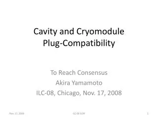
High Pressure Cavity Calibration and MeasurementMCTF MeetingAl Moretti11/06/08
εps εps = Maxium Electric Surface location
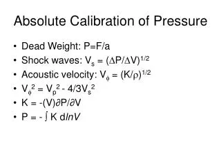
SuperFish Program used for the Calibration: • The geometry is inputted to the program. • The program then Calculates the Qos, εps, Surface Electric Field, EStored energy, Zo Shunt impedance, PLS rf power to produce the above and other factors. • The peak surface field at BreakdownεpB is then given after the Qomeas, Coupling Factor and all attenuation factors of connecting cables are measured on a calibrated network analyzer by: εpB/ εps = √(PLB/PLS) Where PLB by PLB = (AF) Attenuation Factor x Vp²/100 in a 50 Ohm system. • One way of looking at this, SuperFish givesεps for 1 kW disapation on the cavity surfaces and it takes about 250 kW to reach breakdown. εps
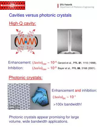
First a Cal. NW Analyzer measurement is made of the Coupling factor (CF) between Terminal A-B, Then a measurement is made of the Attenuation Factor of the three cables to the Control room Terminals A’-C. The 3 cables are combined in 3 combinations, 2 at a time. These cables are then connected to the scope for Vp, Forward and Reverse RF Power. B C 20 DB Pad 15/8” Power Coupler Filter ½” Heliax, 100m long A’ A 3.6 mm Coax Pick-up probe D Breakdown cone Surface The cable measurements are used to determine the attenuation factor of each cable (CA)
LogS11 The graphs show the resonance of a Pill-Box cavity on a log and Smith Cart of S11. The points 3 and 4 on the Log plot represent half of the insertion loss (IL) of the RF power coupler from B-D The point 1 on the Smith Chart represents the impedance of the cavity at resonance and at the Detuned short position. The points 3 and 4 represent the impedance of the cavity off resonance on the High and low frequency side of the cavity. These are used to determine Qomeas from the formula on side #2: β = ((R1 + (R3 + R4)/2))/50 3 1 4 Smith Chart S11
In this case the Cal NW analyzer, in the Q measurement mode is used to determine QLmeas and CF Cal. NW Analyzer Measurement of S21 of QLmeas and CF
For each electrode material, measurements at the start were made with the high pressure Muoninc cavity pressurized with N2 gas at 5 pressures and 5 Resonant frequencies to span the frequency range of the measurement about 10 MHz. Al the parameter shown on slides # 5 and 6 where measured at the 5 frequencies. They were then used to determine the attenuation factor (AF) (Side#3) and Qomeas. AF= CF + CA –IL/2 in Log10 format. PLB = Anti Log(AF) x Vp²/100 β= ((R1 + (R3 + R4)/2))/50 Qomeas = QLmeas (1 + β ) εpB/ εps = √(PLB/PLS)
Some Error Analysis on IL This represents the calibration runs of IL (insertion loss) for the cavity RF power coupler for the 3 materials under test. The data was taken at the start of each test with a NW analyzer By pressurizing the cavity with N2 gas to span the frequency range of the final high power high pressure testing. It is very probable that none of the test frequencies correspond to the test points on the graph. Worst case error is 0.56dB/2 or +/- 3.3 %.
Summary of Errors This graph represents the combined Qomeas for Al and Sn. Assuming that the electrical conductivity of the Al and Sn sample surfaces were the same, this will give a worst case error estimate for Qomeas of +/- 1%. Similar analysis of R3 and R4, error +/- 1 % Similar analysis of CA, error of +/- 0.5% CF error of +/- 0.5 % IL error of +/- 3.3 % NW Analyzer error of +/- 1.0% Scope error of +/- 2 % SuperFish error of +/-0.2%
Possible breakdown gradient over “Breakdown Cone Surface” SurperFish normalized breakdown gradient relative to the “Breakdown Cone Surface” radius. Spark damage has been seen on most samples out to about 5 mm. This says that the width of the breakdown curves in out graphs should have width of about 5 %.