Download
1 / 24
240 likes | 511 Views
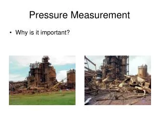
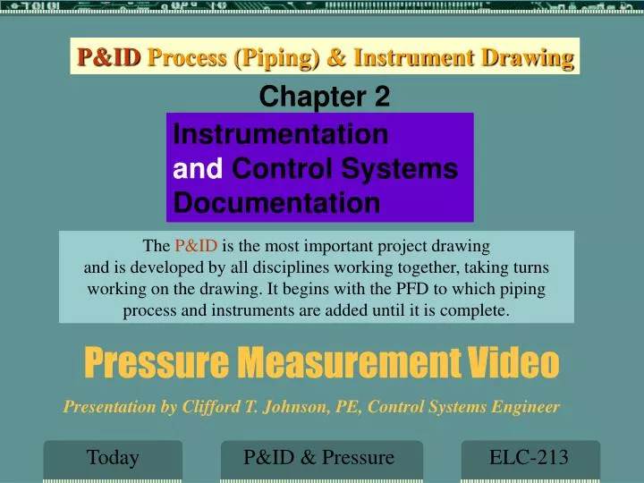
Pressure Measurement Video. P&ID Process (Piping) & Instrument Drawing. Chapter 2. Instrumentation and Control Systems Documentation. The P&ID is the most important project drawing

E N D
Pressure Measurement Video P&ID Process (Piping) & Instrument Drawing Chapter 2 Instrumentation and Control Systems Documentation The P&ID is the most important project drawing and is developed by all disciplines working together, taking turns working on the drawing. It begins with the PFD to which piping process and instruments are added until it is complete. Presentation by Clifford T. Johnson, PE, Control Systems Engineer Today P&ID & Pressure ELC-213
Assignment & Lab Piping & InstrumentDrawing (P&ID) Pressure Measurement Quiz & Link www.cpcc.ctjohnson.com Schedule Assignment & Lab ELC-213
Piping & InstrumentDrawing Importance The Piping (sometimes referred to as Process) andInstrumentation Drawing (P&ID) is the overall design document for a process plant. It defines, using symbols and word descriptions, the equipment, piping, and the instrumentation and control system. It is also the key to other documents. For example instrument tag numbers are shown on a P&ID. This tag number is the key to finding additional information about this device on many other documents. The same is true for line and equipment numbers. Description P&ID ELC-213
P&ID Defined The acronym "P&ID" is widely understood within the process industries as the name for the principal document used to define a process - the equipment, piping and all monitoring and control components. The Automation, Systems and Instrumentation Dictionary, 4th edition's definition for a Piping and Instrumentation Drawing (P&ID) describes them. P&IDs show the interconnection of process equipment and the instrumentation used to control the process. There are several ISA standards to follow when developing a P&ID and the primary one id ANSI/ISA-5.1-2009Instrument Symbols and Identification. This is the oracle for anyone documenting a control system Lab P&ID Def ELC-213
Control Defined Set Point Comparing Feedback Control ISCD ELC-213
Sensing & Comparing PV is Temperature or Pressure or Level or Flow SP is the desired Temperature or Pressure or Level or Flow P&ID ICSD ELC-213
P&ID Identification See in Chapter 2 Fig. 2-5: Valve Failure, Method “A” is Primary Fig. 2-7: Identification Letters, Also shown on web site Fig. 2-10: Succeeding Letters, Also shown on web site Fig. 2-12: Devices & Functions Symbols Fig. 2-13: Line Symbols-part 1 & 2 Fig. 2-16: Valve Symbols You must get familiar with all of the above in order to complete the labs in this course and you there will be many quiz questions that you must answer concerning this ISA Standard. Lab P&ID Def ELC-213
Tagging At least one letter from 1st row And at least one letter from 3rd row This chart is on the web site resources ISA Std P&ID Tag Letters ELC-213
ISA Signal Lines NOTE: MS Visio has some ISA symbols, but not all of them, it does have most of the signal symbols ISA Std P&ID Signal Lines ELC-213
Basic Tag Numbering A basic numbering scheme is used for projects that are small and need not incorporate the Area, Unit or Plant identification. FT-2 FT-01 FT-102 or FT 1002 A large project may require tags that identify the Area, Unit or Plant then use a prefix number or letter for such location. a1L-FT-2 (a= Area, 1=Unit, L=Plant) Always refer to the ISA-5.1 2009 Standard for identification letters and symbols ISA Std P&ID Tagging ELC-213
ISA Symbols NOTE: MS Visio has some ISA symbols, but not all of them, it does not have the FIELD symbols ISA Std P&ID Symbols ELC-213
Loop Defined Definition P&ID Loop ELC-213
Sample P&ID Software connections Pneumatic connections Electric connections Capillary tube Shared Display Field Device Drawing P&ID ELC-213
P&ID Level Loop Drawing P&ID Level Loop ELC-213
P&IDDrawing of Flow Lab to do Remove all instructions Remove all instructions Remove Instructions Lab P&ID Drawing ELC-213
P&ID template to download Download template by clicking on the”X” for the one you want to work with, Be sure to fill in Title Block correctly P&ID Template Drawing ELC-213
PID Control Modes Defined (Not P&ID) This course will concentrate on “PID MODES of CONTROL” • Proportional (GAIN) • Integral (RESET) • Derivative (RATE) NOT to be confused with P&ID Modes PID Control ELC-213
LAB Requirements Download the drawing you want form Resources by clicking on “X” on the resources web page. Use A drawing app to complete You may use Visio, Autocad, Open Office Draw. To complete drawing, be sure to remove instructions if you do not insert your last name, proper subject (bolded on web) and assignment date you may lose an additional 1-3 points. Make sure the email subject is also correct. The email subject should be the same as the one on the drawing Lab ID Requirements ELC-213
You may use any 3 digit number in addtion to “P&ID” for the drawing LAB Title Block You must assign a drawing number that will be used throughout the rest of the course to the P&ID, this same drawing will be used several times Lab Title Block ELC-213
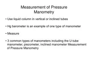
Pressure Measurement Video & Quiz ISA (international Society for Automation) {formally the Instrument Society of America 2nd in a series of four videos Pressure Measurements Download the Pressure Measurement pdf file from the web site, then answer the 10 questions at the end of the file and email to me by Sunday. Quiz Answers Measurement ELC-213
Pressure Measurement You will be working with Pressure Transmitters and Transducer in the lab Make notes of pressure low ranges in Inches of Water and Head Pressures you will be using for calibration, also what URV and LRV stands for Transmitter That you will be calibrating Pressure gauges used to calibrate transmitters Quiz Answers Measurement ELC-213
Homework ASSIGNMENT Web Link Find an example of a Pressure indicator; transmitter; controller; or transducer on the web, email web page LINK only to me, do NOT email images or web pages All Emails Subjects and File names must have Subject:Yourlast Name-Subject-AssignmentDate (AD) Email subject Ex: Johnson-Press-AD Assignment date Lab file name Ex: Johnson-P&ID-AD.vsd You will lose 1-3 points for incorrect subject Subject Assignment ELC-213
My Email Address Cliff.johnson@cpcc.edu Important: DOemail me if you are going to be late or miss a class, if you do not let me know your status before class you may not be able to make up the quiz. Celphone: 980-939-5184 Contact Instructor ELC-213
The End End Instrumentation ELC-213