Download
1 / 8
350 likes | 1.67k Views
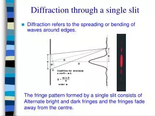
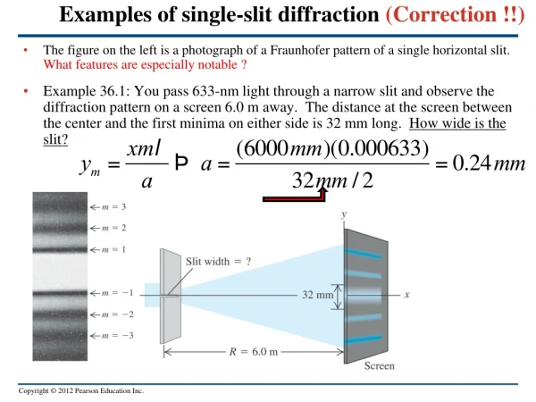
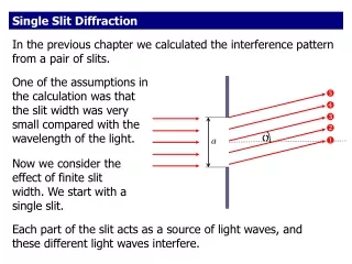
. . . . . a. . Single Slit Diffraction. In the previous chapter we calculated the interference pattern from a pair of slits. One of the assumptions in the calculation was that the slit width was very small compared with the wavelength of the light.

E N D
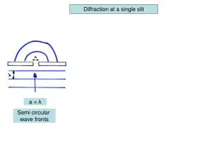
a Single Slit Diffraction In the previous chapter we calculated the interference pattern from a pair of slits. One of the assumptions in the calculation was that the slit width was very small compared with the wavelength of the light. Now we consider the effect of finite slit width. We start with a single slit. Each part of the slit acts as a source of light waves, and these different light waves interfere.
Divide the slit in half. Ray travels farther* than ray by (a/2)sin. Likewise for rays and . a/2 a a/2 If this path difference is exactly half a wavelength (corresponding to a phase difference of 180°) then the two waves will cancel each other and destructive interference results. Destructive interference: *All rays from the slit are converging at a point P very far to the right and out of the picture.
If you divide the slit into 4 equal parts, destructive interference occurs when If you divide the slit into 6 equal parts, destructive interference occurs when Destructive interference: a/2 a a/2
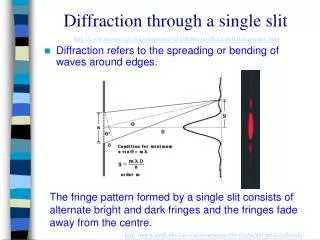
a/2 a a/2 In general, destructive interference occurs when The above equation gives the positions of the dark fringes. The bright fringes are approximately halfway in between. Applet.
Use this geometry for tomorrow’s single-slit homework problems. y a If is small,* then it is valid to use the approximation sin . ( must be expressed in radians.) O x *The approximation is quite good for angles of 10 or less, and not bad for even larger angles.
Single Slit Diffraction Intensity Your text gives the intensity distribution for the single slit. The general features of that distribution are shown below. Most of the intensity is in the central maximum. It is twice the width of the other (secondary) maxima.