Download
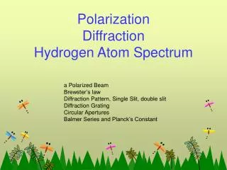
1 / 28
320 likes | 506 Views
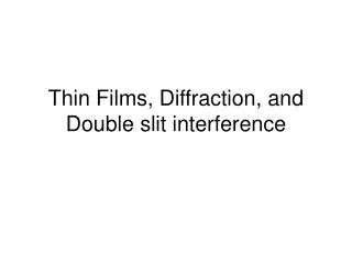
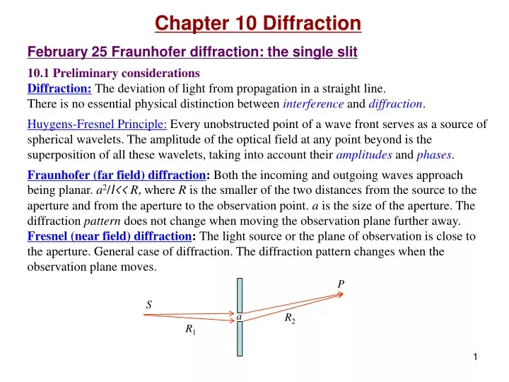
P. S. a. R 2. R 1. Chapter 10 Diffraction February 25 Fraunhofer diffraction: the single slit 10.1 Preliminary considerations Diffraction: The deviation of light from propagation in a straight line. There is no essential physical distinction between interference and diffraction .

E N D
P S a R2 R1 Chapter 10 Diffraction February 25 Fraunhofer diffraction: the single slit 10.1 Preliminary considerations Diffraction:The deviation of light from propagation in a straight line. There is no essential physical distinction betweeninterference and diffraction. Huygens-Fresnel Principle: Every unobstructed point of a wave front serves as a source of spherical wavelets. The amplitude of the optical field at any point beyond is the superposition of all these wavelets, taking into account their amplitudes and phases. Fraunhofer (far field) diffraction:Both the incoming and outgoing waves approach being planar. a2/l<< R, where R is the smaller of the two distances from the source to the aperture and from the aperture to the observation point. a isthe size of the aperture. The diffraction pattern does not change when moving the observation plane further away. Fresnel (near field) diffraction: The light source or the plane of observation is close to the aperture. General case of diffraction. The diffraction pattern changes when the observation plane moves.
y P (x,y) D/2 r dy' x -D/2 P S y' y'sinq Mathematical criteria for Fraunhofer diffraction: The phase for the rays meeting at the observation point is a linear function of the aperture variables: Waves from a point source: Harmonic spherical wave: A is called the source strength. Coherent line source: eL is the source strength per unit length. This equation changes a diffraction problem into an integration (interference) problem.
y P (x,y) D/2 r y' x -D/2 In the phase, r is approximated by R-y'sinq, if D2/Rl <<1. Fraunhofer diffraction condition. R q In the amplitude, r is approximated by R. The overall phase is the same as that for a point source located at the center of the slit. 10.2 Fraunhofer diffraction 10.2.1 The single slit The slit is along the z-axis and has a width of D. Integrate over z gives the same function.
y P (x,y) D/2 r y' x -D/2 I/I(0)= 0.047 0.016 b R q Example 10.1
Phasor model of single slit Fraunhofer diffraction: rolling paper
Read: Ch10: 1-2 Homework: Ch10: 2,7,8,9 Due: March 8
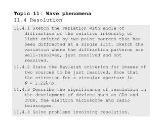
z P (x,z) R-asinq b R a q x March 4 Double slit and many slits 10.2.2 The double slit The result is a rapidly varying double-slit interference pattern (cos2a) modulated by a slowly varying single-slit diffraction pattern (sin2b/b 2).
Two-slitinterference Single-slit diffraction Fringes Envelope Question: Which interference maximum coincides with the first diffraction minimum? “Half-fringe” (split fringe) may occur there. Our author counts a half-fringe as 0.5 fringe. half-fringe
P (x,z) z R-2asinq R-asinq b R a q x 10.2.3 Diffraction by many slits
a Principle maxima: Minima (totally N-1): Subsidiary maxima (totally N-2): Example 10.3
Read: Ch10: 2 Homework: Ch10: 14,15,17 Due: March 22
Y y P(Y,Z) dS=dydz r R x z Z March 6 Rectangular aperture and circular aperture 10.2.4 The rectangular aperture Coherent aperture: X Fraunhofer diffraction condition
Y y P(Y,Z) dS=dydz r R b x a z Z Rectangular aperture:
Y minimum: Z minimum:
Y y 10.2.5 The circular aperture Importance in optical instrumentation: The image of a distant point source is not a point, but a diffraction pattern because of the limited size of the lenses. P(Y,Z) q r R F q f x a z Z Bessel functions:.
J0(u) J1(u) u q1 0.018 3.83 Radius of Airy disk: P D f Example 10.6
Read: Ch10: 2 Homework: Ch10: 25,28,40 Due: March 22
March 8 Resolution of imaging systems 10.2.6.0 Equivalence between the far field and the focal plane diffraction pattern Two coherent point sources: P y R a q asinq L P' y' a q q • This applies to any number of arbitrarily distributed point sources in space. • Far field and focal plane produce the same diffraction pattern, but with different sizes. • R is replaced by f in the focal plane pattern. A lens pulls a far-field diffraction pattern to its focal plane, reduces the size by f/R. asinq f
P2 S1 D S2 P1 P P D D f f 10.2.6 Resolution of imaging systems Image size of a circular aperture: Rayleigh’s criterionfor bare resolution: The center of one Airy disk falls on the first minimum of the other Airy disk. We can actually do a little better. Image size of a far point source: far away f Angular limit of resolution: Overlap of two incoherent point sources:
Angular limit of resolution: 150mm Human cone photoreceptor cells Wavelength dependence: CD DVD Our eyes: About 1/3000 rad Example 10.7 Pupil diameter Focal length Spot distance on the retina: 20 mm/3000=6.7mm Space between human photoreceptor cells on the retina: 5-7mm. Pixel size of a CCD camera: ~7.5 mm.
Read: Ch10: 2 Homework: Ch10: 42,46,49 Due: March 22
a qm qi a a qm g specular qi qi qr q0 0th March 18, 20 Gratings Diffraction grating:An optical device with regularly spaced array of diffracting elements. Transmission gratings and reflection gratings. Grating equation: 2 1 m=0 -1 -2 Blazed grating:Enhancing the energy of a certain order of diffraction. Blaze angle: g Specular reflection:
Angular width of a narrow spectral line due to instrumental broadening. Inversely proportional to Na. dqm dl Grating spectroscopy: Angular width for a spectral line due to instrumental broadening: N-slit interference Between two minima, (N-1)p/N to (N+1)p/N . l Dq Angular dispersion between different spectral lines:
Limit of resolution: Barely resolved two close wavelengths: Resolving power: (Dq)separation (Dq)width Dl The resolving power of a grating increases with increasing order number and with increasing number of illuminated slits.
fsr m =3 m =2 m =1 sinqm Free spectral range: The widest spectrum that can be studied without confusing the order of diffraction. mth order of the red end overlaps with the m+1 th order of the blue end of the spectrum: l l+Dl In higher order diffraction the spectrum is more spread in angle. This results in a higher resolving power but a narrower free spectral range. Example 10.9
Read: Ch10: 1-2 Homework: Ch10: 55,56,59,66,68 Due: March 29
La nature ne s'est pas embarrassée des difficultés d'analyse. Nature is not embarrassed by difficulties of analysis. Augustin Fresnel