Download
1 / 35
390 likes | 1.24k Views
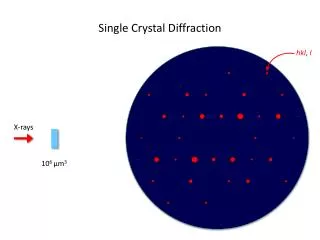
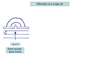
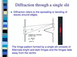
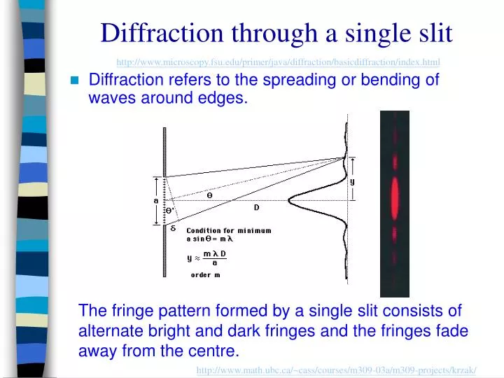
Diffraction through a single slit. http://www.microscopy.fsu.edu/primer/java/diffraction/basicdiffraction/index.html. Diffraction refers to the spreading or bending of waves around edges. The fringe pattern formed by a single slit consists of

E N D
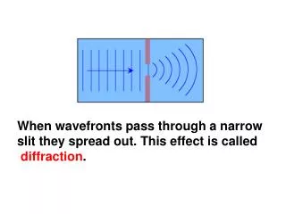
Diffraction through a single slit http://www.microscopy.fsu.edu/primer/java/diffraction/basicdiffraction/index.html • Diffraction refers to the spreading or bending of waves around edges. The fringe pattern formed by a single slit consists of alternate bright and dark fringes and the fringes fade away from the centre. http://www.math.ubc.ca/~cass/courses/m309-03a/m309-projects/krzak/
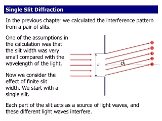
Diffraction patterns from slits of different widths. • Narrow gap compared to wavelength – large diffraction effect • Condition for minimum: • Sin = n/a • y/d n/a
Intensity Source 1 Source 2 Distance Resolution and Diffraction • Resolution refers to the ability to distinguish two objects that are close together. • The light from an object is diffracted by the aperture of the viewing instrument. • Two neighbouring objects can be resolved provided that the peak from the central maximum of one is no closer than the first minimum of the other (and vice versa).
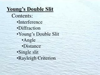
Young’s experiment http://vsg.quasihome.com/interfer.htm http://www.matter.org.uk/schools/Content/Interference/doubleslits_1.html
Light source Single slit Schematic diagram of Young’s double-slit experiment http://qbx6.ltu.edu/s_schneider/physlets/main/doubleslitintensity.shtml http://www.walter-fendt.de/ph11e/interference.htm
Conditions for Observable Interference • Coherent Sources • Coherent sources are those which emit light waves of the same wavelength or frequency and are always in phase with each other or have a constant phase difference. • Polarization • The wave disturbance have the same polarization. • Amplitudes • The two sets of wave must have roughly equal amplitude. • Path Difference • The path difference between the light waves must not be too great. http://www.ngsir.netfirms.com/englishhtm/Interference.htm
Appearance of Young’s interference Fringes http://micro.magnet.fsu.edu/primer/java/interference/doubleslit/index.html • If the source slit is moved nearer to the double slits the separation of the fringes is unaffected but their brightness increases. • If the separation of the double slits decreases, the separation of the fringes increases. • If the width of slits is widened, the number of fringes decreases. • If white light is used the central fringe is white and the fringes on either side are coloured.
Interference by Thin Films Thin film of soapy water Seashell • Thin film interference patterns seen in A thin layer of oil on the Water of a street puddle
t Parallel-sided Thin Film (1) When a beam of light is incident on to the surface of the film, part of incident light is reflected on the top surface and part of that transmitted is reflected on the lower surface. • Consider a film of soap with uniform thickness in air air If the film is not too thick, the two reflected beams produces an interference effect. Soap film http://webphysics.davidson.edu/physlet_resources/bu_semester2/c26_thinfilm.html
Parallel-sided Thin Film(2) • If light travelling in a less dense medium is reflected by a dense medium, the reflected wave is phase-shifted by π. • If light travelling in a dense medium is reflected by a less dense medium, the reflected wave does not experience any phase shift.
Parallel sided Thin Film (3) • Constructive interference occurs if the path difference between the two reflected light beams is Where n = 0, 1, 2, … • Destructive interference occurs if the path difference between the two reflected light beams is Where n = 0, 1, 2, … • If the film has a refractive index μ then we get
Parallel sided Thin Film (4) • On the other hand, the part reflected at the lower surface must travel the extra distance of 2 t, where t is the thickness of the film. • That is, 2t is the path difference between the two reflected beams. • If 2t = (n+½)λ then constructive interference occurs. • If 2t = nλ then destructive interference occurs. • When t is large, several values of λ satisfy the equation. The film will appear to be generally illuminated.
Blooming of Lenses (1) • The process of coating a film on the lens is called blooming. • A very thin coating on the lens surface can reduce reflections of light considerably. http://mysite.verizon.net/vzeoacw1/thinfilm.htmll
Blooming of Lenses (2) • The amount of reflection of light at a boundary depends on the difference in refractive index between the two materials. • Ideally, the coating material should have a refractive index so that the amount of reflection at each surface is about equal. Then destructive interference can occur nearly completely for one particular wavelength. http://qbx6.ltu.edu/s_schneider/physlets/main/index.shtml
Blooming of Lenses (3) • The thickness of the film is chosen so that light reflecting from the front and rear surfaces of the film destructively interferes. • For cancellation of reflected light,
Thin Film of Air, Wedged-shaped (1) • Light rays reflected from the upper and lower surfaces of a thin wedge of air interfere to produce bright and dark fringes. • The fringes are equally spaced and parallel to the thin end of the wedge. http://www.gg.caltech.edu/~zhukov/applets/film/applet.html
θ t Thin Film of Air, Wedged-shaped (2) http://www.phy.ntnu.edu.tw/ntnujava/index.php?topic=204.0 • For minimum intensity, 2t = nλ. • For maximum intensity, 2t = (n+½)λ. Fringe Spacing, d
Newton’s Rings (1) • When a curved glass surface is placed in contact with a flat glass surface, a series of concentric rings is seen when illuminated from above by monochromatic light. These are called Newton’s rings. http://www.phy.ntnu.edu.tw/ntnujava/index.php?topic=1433.msg5413#msg5413
Newton’s Ring (2) • Newton’s rings are due to interference between rays reflected by the top and bottom surfaces of the very thin air gap between the two pieces of glass. • Newton’s rings represent a system of contour fringes with radial symmetry. • The point of contact of the two glass surfaces is dark, which tells us the two rays must be completely out of phase.
Flatness of Surfaces • Observed fringes for a wedged-shaped air film between two glass plates that are not flat. • Each dark fringe corresponds to a region of equal thickness in the film. • Between two adjacent fringes the change in thickness is λ/2μ. where μ is the refractive index of the film.
Multiple Slits (1) Three-slit pattern Double slit pattern The fringes of the double slit pattern fade away from centre and disappear at the single slit minimum. There is a subsidiary maximum between the double slit maxima.The fringes become narrower and sharper. http://www.matter.org.uk/schools/Content/Interference/gratings.html
Multiple Slits (2) • The fringes become sharper as the number of slits is increased. • The subsidiary maxima become less and less significant as the number of slits is increased. http://www.matter.org.uk/schools/Content/Interference/gratingExplored.html
Diffraction Grating • A large number of equally spaced parallel slits is called a diffraction grating. • A diffraction grating can be thought of as an optical component that has tiny grooves cut into it. The grooves are cut so small that their measurements approach the wave length of light.
Diffraction Gratings http://www.launc.tased.edu.au/online/sciences/physics/diffra/diffrac.htm • A diffraction grating splits a plane wave into a number of subsidiary waves which can be brought together to form an interference pattern.
X θ θ Y d θ Path difference = d sin θ Action of Diffraction Grating • If d is the slit spacing then the path difference between the light rays X and Y = d sin θ. • For principal maxima, d sin θ = nλ. • The closer the slits, the more widely spaced are the diffracted beams. • The longer the wavelength of light used, the more widely spaced are the diffracted beams.
n = 2 n = 1 θ2 θ1 n = 0 θ1 θ2 n = 1 n = 2 Number of Diffraction beams • Since sin θ 1, • The highest order number is given by the value of d/λ rounded down to the nearest whole number.
Intensity of Diffraction Grating Pattern http://micro.magnet.fsu.edu/primer/java/diffraction/diffractionorders/index.html
View through Diffraction Grating • Diffraction grating placed in front of a methane air flame • Spectrum of a star • - Procyon
Turntable Diffraction grating Collimator C θ Light source Telescope T Eyepiece Achromatic lenses Eye Cross-wire Using a diffraction grating to measure the wavelength of light • A spectrometer is a device to measure wavelengths of light accurately using diffraction grating to separate.
Line Spectrum • The appearance of the spectrum in a spectroscope (spectrometer) 656 nm Hydrogen 486 nm 588 nm Neon http://jersey.uoregon.edu/vlab/elements/Elements.html