Download
1 / 7
70 likes | 75 Views
The main objective of the project is to design and draft a fully functional Heating, Ventilation and Air Conditional HVAC system for computer center. From residential to commercial structures such as apartments, laboratories, hospitals, etc..., can be designed with HVAC components. HVAC is used to adjust the comfort level of both ambient temperature and air humidity to feel comfortable in enclosed spaces. As we want the heating, cooling, and ventilating system to perform well, we needed to start with an efficient duct design. In this project, we designed a duct system using the protocols based on ISHRAE Indian Society of Heating Refrigeration and Air conditioning Engineers and ASHRAE American Society of Heating Refrigeration and Air conditioning Engineers standards. The underlying principle was to design a duct system, which delivers the correct Cubic Feet per Minute CFM air flow to the residential building against the friction created by the ducts and fittings, with the static pressure available from the blower. When there is more surface area exposed to the air flow from the blower, amount of friction will increase and the blower must work more competently to achieve the required air flow. To provide greater air flow by overcoming the friction, radius elbow ducts are used, which provides smooth radius ensuring uniformity of air flow, reduces turbulence which in turn results in very low pressure drop. For Duct design calculations we used AUTO DESK REVIT design software. For space references and calculations, Autodesk Revit plan was taken from the civil department and the position of duct was identified. Based on the obtained Heat Load Calculations and cubic feet per minute are calculated by using E 20 form sheet and by using ISHRAE handbook, duct sizes were design and chiller size was estimated for residential building. Srihari. M | Md. Irshad | K. Mahesh | K. Sai Teja "Design of Chiller for Air-Conditioning of Residential Building" Published in International Journal of Trend in Scientific Research and Development (ijtsrd), ISSN: 2456-6470, Volume-3 | Issue-3 , April 2019, URL: https://www.ijtsrd.com/papers/ijtsrd23291.pdf Paper URL: https://www.ijtsrd.com/engineering/mechanical-engineering/23291/design-of-chiller-for-air-conditioning-of-residential-building/srihari-m<br>

E N D
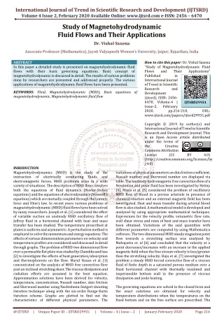
International Journal of Trend in Scientific Research and Development (IJTSRD) Volume: 3 | Issue: 3 | Mar-Apr 2019 Available Online: www.ijtsrd.com e-ISSN: 2456 - 6470 Design of Chiller for Air-Conditioning of Residential Building Srihari. M1, Md. Irshad2, K. Mahesh2, K. Sai Teja2 1Assistant Professor, 2Student 1, 2Department of Mechanical Engineering, Guru Nanak Institute of Technology, Hyderabad, India How to cite this pape: Srihari. M | Md. Irshad | K. Mahesh | K. Sai Teja "Design of Chiller for Air-Conditioning of Residential Building" Published in International Journal of Trend in Scientific Research and Development (ijtsrd), ISSN: 2456- 6470, Volume-3 | Issue-3, April 2019, pp.1246-1252, URL: https://www.ijtsrd.c om/papers/ijtsrd23 291.pdf Copyright © 2019 by author(s) and International Journal of Trend in Scientific Research and Development Journal. This is an Open Access article distributed under the terms of the Creative Commons Attribution License (CC BY 4.0) (http://creativecommons.org/licenses/ by/4.0) I. INTRODUCTION Heat Ventilation and Air Conditioning Air conditioning is used in most commercial properties, ranging from small shops and cafes to large office buildings and public spaces. To meet these dive applications, air conditioning systems have different heating and cooling capacities and come with various setups and layouts Many of our homes and most offices and commercial facilities would not become fordable without control of the indoor environment. The luxury label attached to air conditioning in earlier decades has given way to appreciate it practicality in making our live healthier and more productive. Along with rapid development in improving human comfort came the realization that goods could be produced better, faster, and more economically in a properly controlled environment. ABSTRACT The main objective of the project is to design and draft a fully functional Heating, Ventilation and Air Conditional (HVAC) system for computer center. From residential to commercial structures such as apartments, laboratories, hospitals, etc..., can be designed with HVAC components. HVAC is used to adjust the comfort level of both ambient temperature and air humidity to feel comfortable in enclosed spaces. As we want the heating, cooling, and ventilating system to perform well, we needed to start with an efficient duct design. In this project, we designed a duct system using the protocols based on ISHRAE (Indian Society of Heating Refrigeration and Air- conditioning Engineers) and ASHRAE (American Society of Heating Refrigeration and Air-conditioning Engineers) standards. The underlying principle was to design a duct system, which delivers the correct Cubic Feet per Minute (CFM) air flow to the residential building against the friction created by the ducts and fittings, with the static pressure available from the blower. When there is more surface area exposed to the air-flow from the blower, amount of friction will increase and the blower must work more competently to achieve the required air-flow. To provide greater air-flow by overcoming the friction, radius elbow ducts are used, which provides smooth radius ensuring uniformity of air flow, reduces turbulence which in-turn results in very low pressure drop. For Duct design calculations we used AUTO_DESK REVIT design software. For space references and calculations, Autodesk Revit plan was taken from the civil department and the position of duct was identified. Based on the obtained Heat Load Calculations and cubic feet per minute are calculated by using E- 20 form sheet and by using ISHRAE handbook, duct sizes were design and chiller size was estimated for residential building. Keywords: Refrigeration, Duct, Chiller Capacity estimation, Auto-Desk Revit characteristics between the air passing over the coil and liquid passing through the coil. The type of liquid used depends on the system selected. Direct-expansion (DX) equipment uses refrigerant as the liquid medium. Chilled- water (CW) can also be used as a liquid medium. When the required temperature of a chilled water system is near the freezing point of water, freeze protection is added in the form of glycols or salts. Regardless of the liquid medium used, the liquid is delivered to the cooling coil at a cold temperature. IJTSRD23291 In the case of direct expansion equipment, the air passing over the indoor cooling coil heats the cold liquid refrigerant. Heating the refrigerant causes boiling and transforms the refrigerant from a cold liquid to a warm gas. This warm gas (or vapor) is pumped from the cooling coil to the compressor through a copper tube (suction line to the compressor) where the warm gas is compressed. In some cases, an accumulator is placed between the cooling coil and the compressor to capture unused liquid refrigerant and ensures that only vapor enters the compressor. The compression process increases the pressure of the refrigerant vapor and significantly increases the temperature of the vapor. Working of Air Conditioning An air conditioner cools and dehumidifies the air as it passes over a cold coil surface. The indoor coil is an air-to-liquid heat exchanger with rows of tubes that pass the liquid through the coil. Finned surfaces connected to these tubes increase the overall surface area of the cold surface thereby increasing the heat transfer @ IJTSRD | Unique Paper ID – IJTSRD23291 | Volume – 3 | Issue – 3 | Mar-Apr 2019 Page: 1246
International Journal of Trend in Scientific Research and Development (IJTSRD) @ www.ijtsrd.com eISSN: 2456-6470 The compressor pumps the vapor through another heat exchanger (outdoor condenser) where heat is rejected, and the hot gas is condensed to a warm high- pressure liquid. This warm high-pressure liquid is pumped through a smaller copper tube (liquid line) to a filter (or filter/dryer) and then on to an expansion device where the high-pressure liquid is reduced to a cold, low pressure liquid. The cold liquid enters the indoor cooling coil and the process repeats. Types of air conditioning systems 1 Window Air Conditioner 2 Split Air Conditioner 3 Packaged Air Conditioner 4 Central Air Conditioning System Window air conditioner Figure 1.1 shows window air conditioner is the most commonly used air conditioner for single rooms. In this air conditioner all the components, namely the compressor, condenser, expansion valve, evaporator and cooling coil are enclosed in a single box. This unit is fitted in a slot made in the wall of the room, or more commonly a window sill. Split air conditioner The split air conditioner comprises of two parts, the outdoor unit and the indoor unit (Figure 1.2). The outdoor unit fitted outside the room, it comprises the compressor, condenser and expansion valve. The indoor unit comprises the evaporator or cooling coil and the cooling fan. For this unit you don’t have to make any slot in the wall of the room. Further, present day split units have aesthetic appeal and do not take up as much space as a window unit. A split air conditioner can be used to cool one or two rooms [2]. Packaged air conditioner An HVAC designer will suggest this type of air conditioner if you want to cool more than two rooms or a larger space at your home or office. The Figure 1.3 shows there are two possible arrangements with the package unit. In the first one, all the components, namely the compressor, condenser (which can be air cooled or water cooled), expansion valve and evaporator are housed in a single box. The cooled air is thrown by the high capacity blower, and it flows through the ducts laid through various rooms. In the second arrangement, the compressor and condenser are housed in one casing. The compressed gas passes through individual units, comprised of the expansion valve and cooling coil, located in various rooms. Central air conditioning system The Figure 1.4 shows central air conditioning is used for cooling big buildings, houses, offices, entire hotels, gyms, movie theaters, factories etc. If the whole building is to be air conditioned, HVAC engineers find that putting individual units in each of the rooms is very expensive making this a better option. Refrigerant A refrigerant is a substance or mixture, usually a fluid, used in a heat pump and refrigeration cycle. Refrigeration is a process of moving heat from one location to another in controlled conditions. The work of heat transport is traditionally driven by mechanical work, but can also be driven by heat, magnetism, electricity, laser, or other means. In most cycles it undergoes phase transitions from a liquid to a gas and back again. Many working fluids have been used for such purposes Fluorocarbons, chlorofluorocarbons, became commonplace in the 20th century, gerents used in various applications are ammonia, sulfur dioxide, and non-halogenated but they are being phased out because of their ozone depletion effects. Other common refry hydrocarbons such as propane [4].The first refrigerant used were ether, employed by Perkins in his hand- operated vapor-compression machine. In the earlier days, ethyl chloride was used as a refrigerant which soon gave way to ammonia as early as in 1875.A great breakthrough occurred in the field of refrigerants for centrifugal machines. Types of refrigerants The most common types of refrigerants in use nowadays are presented below. Halocarbons are generally synthetically produced. Depending on whether they include chemical elements hydrogen (H), carbon (C), chlorine (Cl) and Fluorine (F) they are named after as follows: CFCs (Chlorofluorocarbons): R11, R12, R113, R114, R115 HCFCs (Hydro chlorofluorocarbons): R22, R123 HFCs (Hydro fluorocarbons): R134a, R404a, R407C, and R410. Duct system Ducts are conduits or passages used in heating, ventilation, and air conditioning (HVAC) to deliver and remove air. The Figure 1.6 shows needed airflows include, for example, supply air, return air, and exhaust air. Ducts commonly also deliver ventilation air as part of the supply air. As such, air ducts are one method of ensuring acceptable indoor air quality as well as thermal comfort. Process duct work conveys large volumes of hot, dusty air from processing equipment to mills, bughouses to other process equipment. Process duct work may be round or rectangular. Although round duct work costs more to fabricate than rectangular duct work, it requires fewer stiffeners and is favored in many applications over rectangular ductwork. The air in process duct work may be at ambient conditions or may operate at up to 900 °F (482 °C). Process ductwork varies in size from 2 ft diameter to 20 ft diameter or to perhaps 20 ft by 40 ft rectangular. Large process ductwork may fill with dust, depending on slope, to up to 30% of cross section, which can weigh 2 to 4 tons per linear foot. Round ductwork is subject to duct suction collapse and requires stiffeners to minimize this. But is more efficient on material than rectangular duct work. Duct Material Galvanized steel (Zn coated) it should be carbon content not more than 0.15% and G60 or G90 are usually used in duct network Stainless steel Types 304 and 316, with 2B finish. Types 304L and316L have lower carbon content for better welding. Type 316 is used for kitchen hoods. especially @ IJTSRD | Unique Paper ID – IJTSRD23291 | Volume – 3 | Issue – 3 | Mar-Apr 2019 Page: 1247
International Journal of Trend in Scientific Research and Development (IJTSRD) @ www.ijtsrd.com eISSN: 2456-6470 Aluminum ductwork is normally 3003 alloys 14 temper per ASTM B 209 with dimensional tolerances of ANSI Standard H 35.2. Normally 6061 alloy T6 temper per SMACNA’s HVAC- DCS (for rectangular ducts for 3 in. w.g. or less). Two-Way Duct Cold-rolled copper ducts are rarely used. Beryllium copper grade C17000 with TH04 temper are used. Fiber glass is used as an insulating material and fabric of these are used directly as in duct design. Carbon fiber can also be used in duct design where high strength is needed and light weight required. Duct Fittings There are mainly 6 types of fittings used in Duct designing Figure 11 2-way duct Shoe piece or Collar Reducer Figure 7 Shoe piece Elbow Figure 12 Reducer CHILLER Figure 8 Elbow Trouser Figure 9 Trouser Three-Way Duct Figure 13 Chilled water air conditioning with cooling tower A chiller is a machine that removes heat from a liquid via a vapor- compression or absorption refrigeration cycle. This liquid can then be circulated through a heat exchanger to cool equipment, or another process stream (such as air or process water). As a necessary by-product, refrigeration creates waste heat that must be exhausted to ambience, or for greater efficiency, recovered for heating purposes. Chilled water is used to cool and dehumidify air in mid- to large-size commercial, industrial, and institutional facilities. Figure 10 3-way duct @ IJTSRD | Unique Paper ID – IJTSRD23291 | Volume – 3 | Issue – 3 | Mar-Apr 2019 Page: 1248
International Journal of Trend in Scientific Research and Development (IJTSRD) @ www.ijtsrd.com eISSN: 2456-6470 Water chillers can be water-cooled, air-cooled, or evaporatively cooled. Water-cooled systems can provide efficiency and environmental impact advantages over air- cooled systems. There are two types of liquid chillers. The former has refrigerant in the shell and liquid to be chilled in the tubes where the latter has refrigerant in the tubes and liquid to be chilled in the shell. When the refrigerant is in the shell, the refrigerant liquid level is so kept that there is enough space on the top portion of the shell for the liquid and vapour to separate. Vapours are drawn from the top portion by the compressor. Liquid level must be maintained constant as the chilled tubes are also immersed in the refrigerant liquid. USE IN AIR CONDITIONING In air conditioning systems, chilled water is typically distributed to heat exchangers, or coils, in air handlers or other types of terminal devices which cool the air in their respective space(s). The water is then recirculated to the chiller to be recooled. These cooling coils transfer sensible heat and latent heat from the air to the chilled water, thus cooling and usually dehumidifying the air stream. A typical chiller for air conditioning applications is rated between 15 and 2000 tons, and at least one manufacturer can produce chillers capable of up to 5,200 tons of cooling. Chilled water temperatures can range from 35 to 45 °F (2 to 7 °C), depending upon application requirements.[4] When the chillers for air conditioning systems are not operable or they are in need of repair or replacement, emergency chillers may be used to supply chilled water. Rental chillers are mounted on a trailer so that they can be quickly deployed to the site. II. Plan layout Materials (Civil Building Material) Many materials are used for the building such as material for walls (i.e Concrete hollow blocks, Cement, sand etc). Window materials (types of glass), Doors (type of door, i.e. wooden, glass etc), material for roof, floor, and partition wall. So for this 3 floor project specifications we have list of materials to be utilized by civil contractor. WINDOW MATERIALS Ordinary glass- outside awing (vented sides top ) medium color. Dimensions of window (L×B): 5ft×3ft. DOOR MATERIALS Wooden Door are utilized for this project. Dimension of Door (L×B): 7ft ×3ft). MASONARY WALL MATERIAL Solid brick by falls and commands of the 123/18‖ plastic on wall sepsis’s board MASONARY PARTITION WALL MATERIAL Concrete blocks of with light weight aggregate of 1/2‖ plaster 6‖ thick MASONARY FLOOR MATERIAL Slab of sand aggregate of 8‖ thick and ½‖ light weight plastic with no furring. TRANSMISSION COEFFICIENT ΔU Transmission coefficient value changes for each type of material used for civil building. So as per ISHRAE/ASHRAE standards, see below data table of transmission coefficient for different materials used for our project. Transmission coefficient Coefficient factor Glass 0.2 Masonry Wall 0.31 Roof 0.30 Partition Wall 0.20 Floor 0.33 BUILDING INFORMATION Lighting load for the application will be provided by the ckient and concern department for electrical. If client doesn’t provided that considered from the standard electrical data book. For residential: 1 to 1.25w/s.ft For commercial: 1.25 to 1.5w/s.ft For industrial: 1.5 to 2.0 w/s.ft Equipment Load Equipment load is categorized either w.r.t the wattage of the Equipment per area depending on the application. The star dart equipment load varies from 0.5w/s.ft to 0.9 w/s.ft depending on application Figure 14 civil plan. Location and Thermal Conditions Building Location : Hyderabad Orientation Application Latitude : Equal share of walls of all sides : Residential Building : 17.86ºN Sp. Daily Range (ºF) DBT (ºF) WBT (ºF) RH (%) Condition Humidity (Gr/Lb) Ambient 106 78 28 100 14 Room Thermal Conditions 75 63 50 65 - Difference 31 15 22 35 - @ IJTSRD | Unique Paper ID – IJTSRD23291 | Volume – 3 | Issue – 3 | Mar-Apr 2019 Page: 1249
International Journal of Trend in Scientific Research and Development (IJTSRD) @ www.ijtsrd.com eISSN: 2456-6470 People Load The no of people occupying the space for residential application is considered w.r.t type for other application the no of people are considered from seating arrangement is given then no of people is considered as 1 person for 30. III. DUCT DESIGN Single Line Diagrams Figure 22 First Floor DLD Figure 18 Ground Floor SLD Figure 23 Second Floor DLD 3D Diagram of Ducting of Residential Building Figure 19 First Floor SLD Figure 24 3D Diagram of Ducting Figure 20 Second Floor SLD Double Line Diagrams Figure 21 Ground Floor DLD @ IJTSRD | Unique Paper ID – IJTSRD23291 | Volume – 3 | Issue – 3 | Mar-Apr 2019 Page: 1250
International Journal of Trend in Scientific Research and Development (IJTSRD) @ www.ijtsrd.com eISSN: 2456-6470 IV. Below results will show that CFM flow rate and TR values of all the Floors and all the Rooms are listed below. Room. No Floor Name 1 2 3 4 5 6 7 8 9 10 11 12 13 14 15 16 17 18 19 20 21 22 23 24 V. CONCLUSION From the above calculations the estimated values are 12734.19 CFM air supply and 24.81 TR capacity machine required. For this Trane CGAM Chiller unit was used to maintain proper air conditioning. It is suitable for 12000- 18000 CFM flow rate and 25-28 TR capacity. In this work the calculated CFM values of each room in each floor by using the E-20 Excel sheets and TR values of each room were calculated. The Capacity of unit required is 24.81 TR approximately but used 25-28 TR machine to avoid the fluctuations in the working. Based on the obtained CFM for each room and for all the floors the Duct Design was done by using AUTO_ DESK REVIT software. All the diagrams were shown in the civil plan .Thus we can reach to a conclusion that our estimated values are enough to establish the air conditioning system in the specified location. By using HVAC system energy consumption of the building is reduced as possible by avoiding unnecessary losses. This is one of the most well designed and most useful methods in the present day installations. STANDARD UNIT FEATURES: GENERAL Trane Chiller Model CGAM026F2 CFM 18897 Number of Fans 2 Number of Compressors 2 Tonnage Capacity 25-28TR RESULTS Room Name Bed Room Living Room Drawing Room Bed Room Bed Room Living Room Drawing Room Bed Room Bed Room Living Room Drawing Room Bed Room Bed Room Living Room Drawing Room Bed Room Bed Room Living Room Drawing Room Bed Room Bed Room Living Room Drawing Room Bed Room TOTAL CFM 507.41 372.80 597.17 463.96 463.96 384.19 597.17 511.51 507.41 372.80 597.17 463.96 463.96 384.19 597.17 511.51 629.64 475.93 756.08 590.40 590.40 501.37 756.08 637.95 12734.19 24.81 TR 0.97 0.83 1.16 0.91 0.91 0.87 1.16 0.98 0.97 0.83 1.16 0.91 0.91 0.87 1.16 0.98 1.13 0.98 1.37 1.09 1.09 1.05 1.37 1.15 GROUND FLOOR (FLAT.NO-1) GROUND FLOOR (FLAT.NO-2) FIRST FLOOR (FLAT.NO-1) FIRST FLOOR (FLAT.NO-2) SECOND FLOOR (FLAT.NO-1) SECOND FLOOR (FLAT.NO-2) DIMENSIONS Length with Trailer Width with Trailer Shipping Weight with Trailer 4580 lbs 234 76‖ VI. [1]ArshaViswambharan, Sheetal Kumar Patidar, Khyati Saxena Sustainable HVAC Systems in Commercial and Residential Buildings. International Journal of Scientific and Research Publications, Volume 4, Issue 4, April 2014 1 ISSN 2250-3153 REFERENCES [2]MOHAN KASHYAP Carbon Fiber Composites for Duct design based on VAV network in HVACs system. [3]Adrenalin, M.M., T.F. Smith, J.M. House, and C.J. Klaussner. 2003. ―Building Energy Use and Control Problems: An Assessment of Case Studies.‖ ASHRAE Transactions, Vol. 109, Pt. 2, pp. 111- 121. [4]Samira Benhadid-Dib and Ahmed Benzaoui / Energy Procedia 18 (2012) 807 – 816. [5]Breuker, M.S and J.E Braun 1999. ―Common Faults and Their Impacts for Rooftop Ai Conditioners‖. International Journals of Heating Ventilation and Air Conditioning and Refrigerating Research, 4(2); 303- 318. [6]Brambly, M.R., D. Hansen, P. Haves, D.R. Holmberg, @ IJTSRD | Unique Paper ID – IJTSRD23291 | Volume – 3 | Issue – 3 | Mar-Apr 2019 Page: 1251
International Journal of Trend in Scientific Research and Development (IJTSRD) @ www.ijtsrd.com eISSN: 2456-6470 S.C. McDonald, K.W. Roth and P. Tortellini. 2005a. Advanced Sensors and Controls for Building Applications: Market Assessment and Potential R&D Pathways, PNNL-15149, Pacific Northwest National Laboratory, Richland, WA. Pacific Northwest National Laboratory, Richland, WA. [9]Jin, X. and Z. Du. 2006. ―Fault Tolerant Control of Outdoor Air and AHU Supply Air Temperature in VAV Air Conditioning Systems Using PCA Method.‖ Applied Thermal Engineering 26(11-12):1226-1237. [7]Jacobs, P. 2003. Small HVAC Problems and Potential Savings Reports. P500-03-082A-25, California Energy Commission, Sacramento, CA. [10]Katipamula, S.M.R. Bramley, and L. Luskay. 2003c. ―Automated Proactive Commissioning of Air Handling Units‖.PNWD-3272, Division, Richland, WA. Also published by the Air Conditioning & Refrigeration Technology. BattellenPacificNorthwest [8]Fernandez, N., M.R. Brambley and S. Katipamula. 2009. Self-Correcting HVAC Controls: Algorithms for Sensors and Dampers in Air-Handling Units, PNNL-19104, @ IJTSRD | Unique Paper ID – IJTSRD23291 | Volume – 3 | Issue – 3 | Mar-Apr 2019 Page: 1252