Download
1 / 43
470 likes | 727 Views
Foundation Design. Building structural system By Dr. Sompote Youwai. Contents. Fundamental of Soil Mechanics Interpretation from Soil Report Subsurface investigation Field and laboratory testing Pile Foundation Design Single Pile Pile Group Fundamental of retaining structure

E N D
Foundation Design Building structural system By Dr. SompoteYouwai
Contents • Fundamental of Soil Mechanics • Interpretation from Soil Report • Subsurface investigation • Field and laboratory testing • Pile Foundation Design • Single Pile • Pile Group • Fundamental of retaining structure • Sheet pile • Diaphragm wall
Additional text book • Das M. B., Foundation Engineering. • Tomlinson, M. J. Foundation Design & Construction • Hunt, Geotechnical Engineering Investigation Handbook. • Handout
Method for Pile Design • Hand Calculation • Finite Element Analysis
2. Foundations for Signature Towers Dubai • Nicknamed “Dancing Towers” • Office 351 m, Hotel 305 m, Residential 251 m high • Piled raft foundations • Bored piles 483 nos., 1.5 m dia, 45 m long • Ground conditions: • 0-10 m: Sand • 10-25 m: Very/Weak Sandstone • 25-30 m: Very/Weak Siltstone • 30-40 m: Very/Weak Conglomerate • >40m: Very/WeakClaystone 75-F Office 65-F Hotel 55-F Residential
Foundation Layout Residential (184 nos) Hotel (126 nos) Office (168 nos)
3DF Mesh 590m 505m 150m No of elements = 32,000 • Pile rafts 5.5 m thick, located at 10 metre below ground level
3DF Mesh Residential Tower Office Tower Hotel Tower Load Pile raft 184 nos. 168 nos. Embedded piles: 1.5 m dia. 45 m long 126 nos.
3DF Outputs Contours of Settlements Residential Tower Office Tower Hotel Tower
3DF Outputs Residential Hotel Office Residential Office Hotel
3DF Outputs Deformations of Office piles Axial forces of Office piles
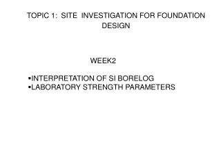
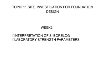
Keyword from boring log • ST, SS • Atterberg’s limits • Water content • Unit weight • Sieve analysis • Unconfined shear • Standard penetration test
Va Vw Vs • Soil is generally a three phase material • Contains solid particles and voids • Voids can contain liquid and gas phases
Va Vw Vs • Soil is generally a three phase material • Contains solid particles and voids • Voids can contain liquid and gas phases
Va Vw Vs • Soil is generally a three phase material • Contains solid particles and voids • Voids can contain liquid and gas phases
Units • Lengthmetres • Masstonnes (1 tonne = 103 kg) • Densityt/m3 • Weightkilonewtons (kN) • Stresskilopascals (kPa) 1 kPa= 1 kN/m2 • Unit weightkN/m3 • AccuracyDensity of water, rw = 1 t/m3 Stress/Strength to 0.1 kPa
Weight and Unit weight • Force due to mass (weight) more important than mass • W = M g • Unit weight
Weight and Unit weight • Force due to mass (weight) more important than mass • W = M g • Unit weight g = r g
Weight and Unit weight • Force due to mass (weight) more important than mass • W = M g • Unit weight g = r g z sv = r g z sv = g z sv
Specific Gravity This is defined by • Gs@2.65 for most soils • Gs is useful because it enables the volume of solid particles to be calculated from mass or weight
Moisture Content • The moisture content, m, is defined as
Moisture Content • The moisture content, m, is defined as In terms of e, S, Gs and gw Ww = gwVw = gwe S Vs Ws = gs Vs = gw Gs Vs
Procedure for grain size determination • Sieving - used for particles > 75 mm • Hydrometer test - used for smaller particles • Analysis based on Stoke’s Law, velocity proportional to diameter
Atterberg Limits • Particle size is not that useful for fine grained soils Moisture content versus volume relation during drying
Atterberg’s Limit • Liquid Limit – The minimum water content at which the soil can be flow under its own weight • Plastic Limit – The minimum water content at which soil can be roller into a thread 3 mm diameter with out breaking up • Shrinkage – The maximum water content at which further loss of moisture does not cause a decrease in the volume of soil
PL – Plastic limit SL – Shrinkage limit
Atterberg Limits SL - Shrinkage Limit PL - Plastic Limit LL - Liquid limit Plasticity Index = LL - PL = PI or Ip Liquidity Index = (m - PL)/Ip = LI
Definition of Grain Size No specific grain size-use Atterberg limits Silt and Clay Gravel Sand Cobbles Boulders Coarse Fine Coarse Medium Fine No.200 0.075 mm No.4 4.75 mm 300 mm 75 mm No.10 2.0 mm 19 mm No.40 0.425 mm
Soil symbols: G: Gravel S: Sand M: Silt C: Clay O: Organic Pt: Peat Liquid limit symbols: H: High LL (LL>50) L: Low LL (LL<50) Gradation symbols: W: Well-graded P: Poorly-graded Symbols Example: SW, Well-graded sand SC, Clayey sand SM, Silty sand, MH, Elastic silt
L H PI LL (Holtz and Kovacs, 1981) Plasticity Chart • The A-line generally separates the more claylike materials from silty materials, and the organics from the inorganics. • The U-line indicates the upper bound for general soils. • Note: If the measured limits of soils are on the left of U-line, they should be rechecked.
Effective stress theory - Fully Saturated: Sr=100% - = Total stress to boundary - u = pore water pressure -u = Effective stress which is transmitted to the soil structure Bishop (1954): ’ = -u : No change in soil strength if no change in ’. f=c’ + ’ tan(’) c’ and ’ are effective cohesion and friction angle of soil. - Equilibrium condition - impermeable membrane
0 50 100 150 kPa 0m 2m 4m Total Stress (5m) pore water pressure 6m Effective stress Depth 8m
z z y x x Stresses acting on a soil element