Download
1 / 20
200 likes | 306 Views
Departure Scenario 1. November 14, 2007. Scenario Overview. Entry of Flight Data into AWIM System Embry Riddle Instructional Flight Delta Flight from Daytona Beach to Atlanta Pre-Pushback Activities Clearance Delivery Aircraft Fueling, Pre-Flight, Start and Pushback

E N D
Departure Scenario 1 November 14, 2007
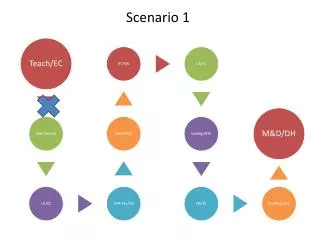
Scenario Overview • Entry of Flight Data into AWIM System • Embry Riddle Instructional Flight • Delta Flight from Daytona Beach to Atlanta • Pre-Pushback Activities • Clearance Delivery • Aircraft Fueling, Pre-Flight, Start and Pushback • Departure Release Coordination • Push-Back • Immediate Push-Back for Embry Riddle Flight • Gate Hold for Just-in-Time Delivery to the Runway for Delta Flight • Taxi • Digital Taxi Clearances • Surface Taxi Trajectories in Surface Automation • Taxi Conformance Monitoring • Take-Off • All Flight Data Objects are Shared between Local Systems through AWIM • And with the Rest of the NAS and Flight Operators through SWIM
Departure Scenario 1 • STEP 1a – Entry of ERAU Flight • ACTION: ERAU Ops Center enters their simulated flight plan into the ERAU flight dispatch system • Flight plan (FP) is transmitted to AWIM • SYSTEM RESPONSE / VISUALIZATION: • ERAU display shows entry of FP • AWIM receives FP and creates a FDO which it adds to the Flight Repository and publishes to all systems connected to AWIM • ERAU FP is displayed in the proposed flight lists of applications connected to AWIM: • EFS, SDSS, CARTS, FPPP and FltWinds • Benefits: • AWIM flight data distributed to all participants • Flight intent data into the NAS
Departure Scenario 1 • STEP 1b – Entry of Commercial Flight • ACTION: Simulated Delta Airlines Ops Center enters their flight plan into the Flight Plan Pre-Processor (FPPP) • Airline receives constraint feedback on 4-D trajectory • Based on Special Activity Airspace • Airspace and airport congestion • SYSTEM RESPONSE / VISUALIZATION: • FPPP display shows entry of Flight Plan • AWIM receives FP and creates a Flight Data Object which it adds to the Flight Repository and publishes to all systems connected to AWIM • Delta FP is displayed in the proposed flight lists of applications connected to AWIM: • EFS, SDSS, CARTS, FPPP and FltWinds • Benefits: • SWIM flight data distributed to all participants • Flight intent data into the NAS • Value of constraint feedback to the airline
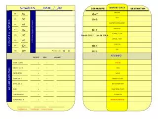
Departure Scenario 1 • STEP 2 – Clearance Delivery for Delta Flight • ACTION: At 10 minutes prior to pushback, the ERAU and Delta pilots each receive clearance via data link • Departure clearance displayed on pilot’s cockpit display • Pilots responds by acknowledging the data link message • SYSTEM RESPONSE / VISUALIZATION: • Flight Data Object is updated automatically • EFS shows flight in ‘Clearance Delivered’ status • Clearance Delivery Controller passes strip to Ground Controller • Benefits: • Reduced operational errors due to digital communication of clearance • No chance for voice/interpretation errors • Improves accuracy of Out and Off time predictions through use of cleared status for TFM use
Departure Scenario 1 • STEP 3 – Departure Readiness • ACTION: The aircraft has a planned door closed / ready to pushback (OUT) time entered in Flight Planning system • SYSTEM RESPONSE / VISUALIZATION: • SDSS computes initial Off Time • Initial Out and Off Time updated in the Flight Data Object and shared with AWIM • Flight Ops enters updated flight status as the phases of turnaround proceed • Benefits: • ATC has awareness of flight’s turnaround status via AWIM
Departure Scenario 1 • STEP 4 – Departure Release Coordination • ACTION: Ramp controller sends request for release to En Route SDSS • En route TMC enters the release time into SDSS • SYSTEM RESPONSE / VISUALIZATION: • En Route SDSS shows flight that is subject to APREQ • Show entry of Release Time • SDSS recalculates OUT, OFF times as needed • EFS displays APREQ release times • Benefits: • Better information to ATC - Earlier request for departure release – possibly capture earlier slot – reduce delay • Just-in-time delivery to the runway end for departure • Reduced emissions – reduced fuel usage
Departure Scenario 1 • STEP 6 – ERAU Power Up and Taxi Start • ACTION: • ERAU ramp clears flight for push-back • Aircraft starts taxiing • SYSTEM RESPONSE / VISUALIZATION: • Aircraft starts generating ADS-B reports • Movement of aircraft is displayed on SDSS, LCSS and CARTS • FDO updated to state ‘Ramp Taxi Out’
Departure Scenario 1 • STEP 7 – ERAU Approaches Spot • ACTION: Tower Ground Controller evaluates taxi route on EFS • Ground Controller modifies taxi route from SDSS which is shown on EFS • SYSTEM RESPONSE / VISUALIZATION: • Taxi Route Change initiates full taxi trajectory update in SDSS • Updated taxi route displayed on EFS • Taxi route changes can be datalinked to the pilot or sent by voice • Benefits: • Automation assistance in generation of taxi routes • Allows for electronic version of taxi route for conformance monitoring
Departure Scenario 1 • STEP 7 – ERAU Approaches Spot (cont.) • ACTION: Aircraft taxis in ramp to spot • Ground Control provides clearance and instructs aircraft to follow SDSS generated surface taxi trajectory • SYSTEM RESPONSE / VISUALIZATION: • Aircraft continues generating ADS-B reports • Movement of aircraft is displayed on SDSS, CAMS and CARTS • Benefits: • Operator (Flt Ops) can now be aware of aircraft status “in the ATC realm” via AWIM • Reduced controller workload due to less frequency interaction
Departure Scenario 1 • STEP 8 – Delta Aircraft power up • ACTION: Aircraft powers up based upon SDSS generated OUT time • SYSTEM RESPONSE / VISUALIZATION: • Aircraft begins generating/broadcasting ADS-B position reports • ADS-B surveillance data is displayed on SDSS, CAMS and CARTS • Benefit: • Just in time power-up – reduced fuel usage and emissions
Departure Scenario 1 • STEP 10 – Delta Push Back • ACTION: Aircraft pushes back • SYSTEM RESPONSE / VISUALIZATION: • Aircraft continues generating ADS-B reports • Movement of aircraft is displayed on SDSS, CAMS and CARTS • FDO updated to state ‘Ramp Taxi Out’ • Benefits • Just-in-time delivery to the runway end for departure • Reduced emissions – reduced fuel usage
Departure Scenario 1 • STEP 11 – Delta Hand Off to Tower Ground Control • ACTION: Tower Ground Controller evaluates taxi route on EFS • Ground Controller approves the taxi route from SDSS which is shown on EFS • SYSTEM RESPONSE / VISUALIZATION: • Taxi route displayed on EFS • Taxi route changes can be datalinked to the pilot or sent by voice • Benefits: • Automation assistance in generation of taxi routes • Allows for electronic version of taxi route for conformance monitoring
Departure Scenario 1 • STEP 12 – Delta Approaches Spot • ACTION: Aircraft taxis in ramp to spot • Ground Control provides clearance and instructs aircraft to follow SDSS generated surface taxi trajectory • SYSTEM RESPONSE / VISUALIZATION: • Aircraft continues generating ADS-B reports • Movement of aircraft is displayed on SDSS, LCSS and CARTS • Benefits: • Operator (Flt Ops) can now be aware of aircraft status “in the ATC realm” via AWIM • Reduced controller workload due to less frequency interaction
Departure Scenario 1 • STEP 13 – Both Flights Follow Surface Taxi Trajectory • ACTION: Aircraft taxies per SDSS generated surface taxi trajectory • EFIS/CDTI/MFD displays taxi clearance • SYSTEM RESPONSE / VISUALIZATION: • Aircraft movement is displayed on SDSS, CAMS and CARTS • SDSS is performing conformance monitoring of aircraft actual position with respect to the assigned surface trajectory • Benefits: • Redundancy of taxi conformance monitoring (ground system and aircraft)
Departure Scenario 1 • STEP 14 – ERAU Flight Taxi Deviation • ACTION: • ERAU Flight taxis to wrong intersection off of taxiway N • SYSTEM RESPONSE / VISUALIZATION: • Aircraft movement is displayed on SDSS, CAMS and CARTS • SDSS performs conformance monitoring of aircraft position • Taxi conformance alert will be shown on SDSS and CARTS • Benefits: • Alerting of taxi deviation immediately upon missing taxi turn – rather than waiting to be approaching runway
Departure Scenario 1 • STEP 15 • ACTION: Aircraft approaching departure queue / run-up area • Flight strip handed off from ground to local on EFS • SYSTEM RESPONSE / VISUALIZATION: • Aircraft movement continues to be displayed on SDSS, CAMS and CARTS • SDSS continued performing conformance monitoring of aircraft actual position versus the surface trajectory
Departure Scenario 1 • STEP 16 – Both ERAU and Delta Line Up for Take Off in Sequence • ACTION: CLEAR TAKEOFF issued by voice by Local Controller • Flight enters runway according to local controller clearance • SYSTEM RESPONSE / VISUALIZATION: • EFS Status Indicates Take-Off Clearance Issued
Departure Scenario 1 • STEP 17 – Flights Take-off in Sequence • ACTION: Aircraft enters runway and takes off • SYSTEM RESPONSE / VISUALIZATION: • ADS-B and MWS position reporting • OFF status identified automatically by SDSS and CAMS • As aircraft passes a parameter height or time after ‘OFF’ runway is deallocated • CARTS will “auto acquire” aircraft on departure and generate a Departure Message that is used by the enroute system to initiate its processing • CARTS will show aircraft on departure route • Benefits: • Taxi trajectory and airborne trajectory are consistent – taxi trajectory delivers the flight to the runway for departure to meet the airborne trajectory
Scenario Summary • Entry of Flight Data into AWIM System • AWIM flight data distributed to all participants • Flight intent data into the NAS • Pre-Pushback Activities • TFM has awareness of flight’s turnaround status via AWIM • Better information to ATC - Earlier request for departure release – possibly capture earlier slot – reduce delay • Push-Back • Just-in-time delivery to the runway end for departure • Reduced emissions – reduced fuel usage • Taxi • Automation assistance in generation of taxi routes • Assigned taxi route available in surface automation for conformance monitoring • Alerting of taxi deviation immediately upon missing taxi turn – rather than waiting to be approaching runway • Take-Off • Taxi trajectory and airborne trajectory are consistent – taxi trajectory delivers the flight to the runway for departure to meet the airborne trajectory