Download
1 / 19
210 likes | 459 Views
Spring School of Spectroscopic Data Analyses 8-12 April 2013 Astronomical Institute of the University of Wroclaw Wroclaw, Poland. The art of cooking spectra with IRAF*. Echelle spectra reduction with IRAF*.

E N D
Spring School of Spectroscopic Data Analyses 8-12 April 2013 Astronomical Institute of the University of Wroclaw Wroclaw, Poland The art of cookingspectra with IRAF* Echelle spectra reduction with IRAF* Warning! This is not the “theory” (if any…) of spectra reduction. I show you just the main steps for the reduction of echelle spectra acquired with a fiber-fed spectrograph and I provide you with a “recipe” for “cooking” (extracting) your spectra *IRAF (Image Reduction and Analysis Facility) is distributed by the National Optical Astronomy Observatories, which is operated by the Association of the Universities for Research in Astronomy, inc. (AURA) under cooperative agreement with the National Science Foundation Giovanni Catanzaro INAF – Osservatorio Astrofisico di Catania Spectroscopic School of Data Analysis
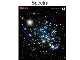
What does reduction mean? We acquired images like this one We want to extract normalized spectra like this one Spectroscopic School of Data Analysis
Typical images acquired during a night • bias • flat field lamp • Calibrationlamp • objects Spectroscopic School of Data Analysis
The reduction process The reduction process consists of a series of operations aimed at removing and/or taking into account the defects and the problems that affect the star signal, before the extraction of the stellar spectrum. These are due both to the optics and the detector. Echelle orders Scattered light Spectroscopic School of Data Analysis
BIAS SUBTRACTION SCATTERED LIGHT SUBTRACTION SPECTRA EXTRACTION DIVISION BY FLAT SPECTRUM WAVELENGTH CALIBRATION NORMALIZATION TO THE CONTINUUM OVERSCAN SUBTRACTION AND IMAGE TRIMMING Basic steps Spectroscopic School of Data Analysis
Exposures with texp=0 sec and closed shutter We produce a “master” bias by averaging the individual bias frames in order to remove cosmic rays.zerocombinetask Bias Spectroscopic School of Data Analysis
Overscan removal The overscan level in ADUs is only an “offset”related to the electronics which reads out the CCD. Its value could slightly change from one line to the other due to very small variations in the reading conditions. We can account for this effect even if it is normally negligible. During this operation, performed with the task ccdproc, we can also trim the image leaving only the true pixels in the final image. The r.m.s of the overscan values is a good measure of the read-out noise in ADUs. In this example we are performing in the same time the overscan and bias removal and the image trimming Spectroscopic School of Data Analysis
Preparing master Flat We average flat frames – which are indeed images of a continuum, featureless spectrum (tungstene or quartz lamp) - after the bias subtraction with the imcombineorflatcombinetask Spectroscopic School of Data Analysis
Scattered light subtraction Scattered light is clearly seen between the spectral orders where the star signal is higher and the orders are closer; it can be due to several causes: dust grains, defects in the optics, spurious orders (ghosts), etc. that bring light away from its path. It can be removed to a very large extent. scattered light contribution to the background Background after subtraction Spectroscopic School of Data Analysis
Aperture finding and tracing We use the apscattertask inside the echelle package We must tell IRAF where the spectral orders are, for evaluating the scattered light in the inter-order regions. The apscattertask allows us both to define the apertures (echelle orders) and to evaluate and subtract the scattered light Spectroscopic School of Data Analysis
Each aperture is traced by fitting the traced points with a Legendrepolynomial For HERMES spectra, I used an order n=7 This fitting has been done for all orders Spectroscopic School of Data Analysis
The level of scattered light is evaluated line by line by fitting the x-cuts where the echelle orders have been removed. A new image, with the fits in each line is temporarily created The vertical cuts of the new image containing the x-cut fits are taken and fitted with a spline. Thus, a 2-dimensional fit of the scattered light is performed and this “smooth” scatter image is subtracted to the original one. Spectroscopic School of Data Analysis
Since the fiber is in a fixed position, for all the other images we can do automatically the subtraction of scattered light taking the previous image (refstar) as a reference for the aperture parameters Whenever the position of the star along the entrance slit changes, one must define the apertures for each individual image Spectroscopic School of Data Analysis
Spectra extraction As for apscatter, for all the other objects we use an input list and extract automatically by choosing an image as aperture and a “profile” reference-frame (for cosmic ray rejection) For object frames: clean yes (Optimal extraction) For flat field and Th-Ar frames: clean no Spectroscopic School of Data Analysis
The echelle blazing has been largely removed. It is much more easy and safe to define a continuum in this spectrum Spectroscopic School of Data Analysis
Wavelength calibration: ThAr (Ne) lamp Spectroscopic School of Data Analysis
We identify for each order some line and then we type “l” to automatically find additional lines in the spectrum, whose wavelength is contained into a file inside IRAF linelists$thar.dat We type “f” to perform a fit of wavelength as a function of pixel number. In the plot the residuals (in Ǻ) are plotted Spectroscopic School of Data Analysis
We assign reference Th-Ar spectra with refspectratask Dispcor is thetask that corrects the dispersion and resample the spectra with a linear dispersion continuumtask normalizes the spectra Spectroscopic School of Data Analysis