Download
1 / 29
300 likes | 306 Views
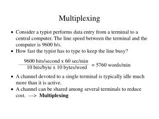
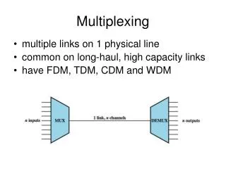
Multiplexing. Chapter 8. Multiplexing. Multiplexing process allows several transmission sources to share a larger transmission capacity . multiple links on 1 physical line Most common use of multiplexing is in long-haul communication using coaxial cable, microwave and optical fibre.

E N D
Multiplexing Chapter 8 Networks and Communication Department
Multiplexing • Multiplexing process allows several transmission sources to share a larger transmission capacity. • multiple links on 1 physical line • Most common use of multiplexing is in long-haul communication using coaxial cable, microwave and optical fibre
Multiplexing • The multiplexer combines (multiplexes) data from the n input lines and transmits over a single data link(medium). • The demultiplexerseparates (demultiplexes) the data according to channel, and delivers data to the appropriate output lines.
Multiplexing Types • Multiplexing :The set of techniques that allows the simultaneous transmission of multiple signals across a single data link. • It has the following types: • 1. Frequency-Division Multiplexing (FDM) • 2. Wavelength-Division Multiplexing (WDM) • 3. Time-Division Multiplexing (TDM) • 4. Code-Division Multiplexing (CDM) Networks and Communication Department
Frequency Division Multiplexing Networks and Communication Department
Frequency Division Multiplexing • FDM can be used with analog signals • Put different signals on different frequency bands using modulations. • each signal is modulated onto a different carrier. • All the modulated signals are combined to form a composite signal for transmission. • signals are carried simultaneously on the same medium • To prevent interference, the channels are separated by guard bands, which are unused portions of the spectrum.
Frequency Division Multiplexing • A general case in Figure 8.2a. Six signal sources are fed into a multiplexer, which modulates each signal onto a different frequency (f1, …, f6).
Frequency Division Multiplexing • Television and radio uses FDM to broadcast many channels over the same media.
Frequency Division Multiplexing Networks and Communication Department
Wavelength Division Multiplexing • Theoretically identical to Frequency Division Multiplexing. • Used in optical systems while FDM is used • in electrical systems. • Requires more spacing between channels • also have Dense Wavelength Division Multiplexing (DWDM)
Time-Division Multiplexing (TDM) • multiple transmissions can occupy a single link by subdividing them and interleaving the portions. • TDM can be implemented in two ways: • 1. Synchronous TDM • 2. Asynchronous TDM Networks and Communication Department
Synchronous Time Division Multiplexing Networks and Communication Department
Synchronous Time Division Multiplexing • can be used with digital signals or analog signals carrying digital data. • In this form of multiplexing, data from various sources are carried in repetitive frames. Each frame consists of a set of time slots, and each source is assigned one or more time slots per frame. • Synchronous TDM is called synchronous not because synchronous transmission is used, but because the time slots are preassignedto sources and fixed.
Synchronous Time Division Multiplexing • The multiplexer allocates exactly the same time slot to each device at all times, whether or not a device has anything to transmit. • A frame consists of one complete cycle of time slots. • Thus the number of slots in frame is equal to the number of inputs. Networks and Communication Department
Synchronous Time Division Multiplexing For example, the multiplexer in Stallings DCC8e Figure 8.2b has six inputs that might each be, say, 9.6 kbps. A single line with a capacity of at least 57.6 kbps (plus overhead capacity) could accommodate all six sources.
How Synchronous TDM Works Networks and Communication Department
Statistical Time Division Multiplexing Networks and Communication Department
Asynchronous TDM(or statistical time-division multiplexing • Each slot in a frame is not dedicated to the fix device • The number of slots in a frame is not necessary to be equal to the number of input devices. • More than one slots in a frame can be allocated for an input device. • Asynchronous TDM (or statistical time-division multiplexing) • Allows maximum utilization of the link. • It allows a number of lower speed input lines to be multiplexed to a single higher speed line Networks and Communication Department
Statistical TDM • in Synch TDM many slots are wasted • Statistical TDM allocates time slots dynamically based on demand • multiplexer scans input lines and collects data until frame full • line data rate lower than aggregate input line rates • may have problems during peak periods • must buffer inputs
How Asynchronous TDM Works? In asynchronous TDM, a frame contains a fix number of time slots. Each slot has an index of which device to receive. Networks and Communication Department
Multiplexing Real Examples Networks and Communication Department
Asymmetrical Digital Subscriber Line (ADSL) • Digital Subscriber Line is the link between subscriber and network • It uses currently installed twisted pair cable • The term asymmetric refers to the fact that ADSL provides more capacity downstream (from the carrier’s central office to the customer’s site) than upstream (from customer to carrier), being a good fit to Internet requirements. • is Asymmetric - bigger downstream than up • uses Frequency division multiplexing • has a range of up to 5.5km
Code Division Multiplexing Networks and Communication Department
Code Division Multiplexing • Sends many signals or “chips” per bit. • Each sender uses a unique pattern of chips. • May use multiple frequencies for spread spectrum communication. • Common with wireless systems. Networks and Communication Department
Any Question ? Networks and Communication Department