Download
1 / 38
701 likes | 1.45k Views
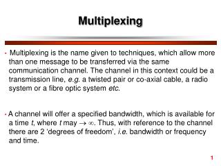
Multiplexing. NETE 0510 Presented by Dr.Apichan Kanjanavapastit. What is Multiplexing. Multiplexing is the set of techniques that allows the simultaneous transmission of multiple signals across a single data link

E N D
Multiplexing NETE 0510 Presented by Dr.Apichan Kanjanavapastit
What is Multiplexing • Multiplexing is the set of techniques that allows the simultaneous transmission of multiple signals across a single data link • Today’s technology includes high-bandwidth media such as optical fiber, each of these has a carrying capacity far in excess of that needed for the average transmission signal • An efficient system maximizes the utilization of all facilities
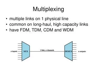
Many to One/One to Many • In a multiplexed system, n devices share the capacity of one link • The stream of traffic from each device is sent to a multiplexer (MUX), which combines them into a single stream (many to one) • At the receiving end, that stream is fed into a demultiplexer (DEMUX), which separates the stream back into its component transmissions (one to many) and directs them to their intended receiving devices
Categories of Multiplexing • Signals are multiplexed using 3 basic techniques: frequency-division multiplexing (FDM), time-division multiplexing (TDM), and wave-division multiplexing (WDM) • TDM is further subdivided into synchronous TDM (usually just called TDM) and asynchronous TDM, also called statistical TDM or concentrator
Frequency-Division Multiplexing (FDM) • FDM is an analog technique • In FDM, signals generated by each sending device modulate different carrier frequencies • Carrier frequencies are separated by enough bandwidth to accommodate the modulated signal
Amplitude Modulation Techniques for Analog Signals • Amplitude Modulation (AM) • Double-sideband suppressed carrier (DSB-SC) modulation • Single-sideband suppressed carrier (SSB) modulation
Amplitude Modulation (AM) AM modulator 0 4 kHz 6 kHz 10 kHz 14 kHz 10 kHz
Double-sideband suppressed carrier modulation (DSB-SC) DSB-SC modulator 0 4 kHz 6 kHz 10 kHz 14 kHz 10 kHz
Single-sideband suppressed carrier (SSB) DSB-SC modulator Band Pass Filter 6 kHz 10 kHz 6 kHz 10 kHz 14 kHz 0 4 kHz SSB 10 kHz
Example#1 • Five channels, each with a 100-kHz bandwidth, are to be multiplexed together. What is the minimum bandwidth of the link if there is a need for a guard band of 10 kHz between the channels to prevent interference?
Example#2 • Four digital signals, each transmitting at data rate of 1 Mbps, use a satellite channel of 1 MHz. Design an appropriate configuration, using FDM.
ITU-T Multiplexing Plan for Analog Telephone System (cont.) Incoming Ch. BPF 104-108 kHz 1 108 kHz BPF Multiplex signal 104-108 kHz 2 104 kHz BPF 104-108 kHz 12 64 kHz 9 8 7 6 5 4 3 2 1 12 11 10 80 84 88 92 96 100 104 108 60 64 68 72 76
12 voice frequency Channel input (0-4 kHz) Supergroup output 60VF. 240 kHz bandwidth 108 F=108 F=3396 3048 2844 F=104 104 F=3148 Group output 12 VF. 48 kHz bandwidth 2836 Mastergroup output 600VF. 2.52 MHz bandwidth 2569 100 F=100 F=2900 2588 F=96 96 2348 F=612 552 F=2652 2340 92 F=92 2100 504 F=564 F=2356 2044 F=88 88 1804 F=516 456 84 F=84 F=2108 1796 408 F=468 1556 F=80 80 F=1860 F=420 360 1548 1308 76 F=76 312 F=1612 1300 5 Group inputs 1060 F=72 72 10 Supergroup inputs F=1364 1052 68 F=68 812 F=1116 Supergroup multiplexer 804 F=64 64 564 60 Mastergroup multiplexer Group multiplexer
Application Example of FDM: Cable TV • Coaxial cable has a bandwidth up to several hundreds megahertz • The bandwidth of the coaxial cable is normally divided into 6 MHz using FDM • Each band provides a TV channel or data transmission
Wave-Division Multiplexing (WDM) • WDM is conceptually the same as FDM, except that the multiplexing and demultiplexing involve light signals transmitted through fiber optic channels • Combining and splitting of light sources are easily handled by a prism
3.0 2.5 2.0 1.5 1.0 0.5 800 900 1000 1100 1200 1300 1400 1500 1600 1700 Recall Attenuation in Optical Fiber First Window Second Window Third Window ATTENUATION (dB/km) WAVELENGTH (nm) 1310nm 1550nm 850nm
Time-Division Multiplexing (TDM) • TDM is a digital process that can be applied when the data rate capacity of the transmission medium is greater than the data rate required by the sending and receiving ends • TDM can be implemented in 2 ways: TDM and asynchronous TDM
Synchronous TDM • In synchronous TDM, the term synchronous has a different meaning from synchronous transmission • Hear synchronous means that the multiplexer allocates exactly the same time slot to each device at all times, whether or not a device has anything to transmit • Time slots are grouped into frames. A frame consists of one complete cycle of time slots
Interleaving in Synchronous TDM • Synchronous TDM can be compared to a very fast rotating switch • As the switch opens in front of a device, that device has the opportunity to send a specified amount of data into the path • The switch moves from device to device at a constant rate and in a fixed order. This process is called interleaving which can be done by bit, by byte, or by any other data unit
Example#3 • The data rate for each input connection is 1 kbps. If 1 bit at a time is multiplexed (a unit is 1 bit), what is the duration of (a) each input slot, (b) each output slot, and (c) each frame?
Example#4 • The figure below shows synchronous TDM with a data stream for each input and one data stream for the output. The unit of data is 1 bit. Find (a) the input bit duration, (b) the output bit duration, (c) the output bit rate, and (d) the output frame rate.
Example#5 • Four channels are multiplexed using TDM. If each channel sends 100 bytes /s and we multiplex 1 byte per channel, show the frame traveling on the link, the size of the frame, the duration of a frame, the frame rate, and the bit rate for the link.
Example#6 • A multiplexer combines four 100-kbps channels using a time slot of 2 bits. Show the output with four arbitrary inputs. What is the frame rate? What is the frame duration? What is the bit rate? What is the bit duration?
Example#7 • Two channels, one with a bit rate of 100 kbps and another with a bit rate of 200 kbps, are to be multiplexed. How this can be achieved? What is the frame rate? Whatis the frame duration? What is the bit rate of the link?
Framing Bits in Synchronous TDM • Because the time slot order in a synchronous TDM system does not vary from frame to frame, very little overhead information needs to be included in each frame • However, various factors can cause timing inconsistencies. For this reason, one or more synchronization bits are usually added to the beginning of each frame
Framing Bits in Synchronous TDM (cont.) • These bits, called framing bits, that allows the demultiplexer to synchronize with the incoming stream so that it can separate the time slot accurately • In most cases, this synchronization information consists of one bit per frame, alternating between 0 and 1
Example of a Data Rate Calculation in Synchronous TDM • There are 4 input sources on a synchronous TDM link, where transmissions are interleaved by character • If each source is creating 250 characters per second, and each frame is carrying 1 character from each source, the transmission path must be able to carry 250 frames per second • Assuming that each frame is 33 bits long: 32 bits for the 4 characters plus 1 framing bit; the data rate of the multiplexed line will be 8250 bps (250 frames with 33 bits per frame)
Bit Stuffing in Synchronous TDM • Recall that the time-slot length is fixed and it is possible to connect devices of different data rate to a synchronous TDM • For this technique to work, the different data rates must be integer multiples of each other • When the speeds are not integer multiple of each other, they can be made to behave as if they were, by a technique called bit stuffing
Bit Stuffing in Synchronous TDM (cont.) • The multiplexer adds extra bits to a device’s source stream to force the speed relationships among the various devices into integer multiples of each other • The extra bit are then discarded by the demultiplexer
Asynchronous TDM • In synchronous TDM, since the time slots are preassigned and fixed, whenever a connected device is not transmitting, the corresponding slot is empty and that much of the path is wasted • Asynchronous TDM or statistical TDM is designed to avoid this type of waste • In this context, asynchronous means flexible or not fixed • The number of time slots in asynchronous TDM frame is based on a statistical analysis of the number of input lines that are likely to be transmitting at any given time
Asynchronous TDM (cont.) • Like synchronous TDM, asynchronous TDM allows a number of lower-speed input lines to be multiplexed to a single higher-speed line • Unlike synchronous TDM, the total speed of the input lines can be greater than the capacity of the path • In asynchronous TDM, the frame can contain a lower number of time slots when compared with synchronous TDM
Addressing and Overhead in Asynchronous TDM • Addressing and Overhead • In the absence of fixed positional relationships, each time slot must carry an address telling the demultiplexer how to direct the data.