Download
1 / 56
1.12k likes | 2.25k Views
PROGRAMMING WITH 8085. BTCS-404 (MALP) B.Tech 4th SEM. IT Ajay Kumar Dogra Associate Professor, CSE BEANT COLLEGE OF ENGG. & TECH. GURDASPUR. Assembly Language Programming of 8085. Topics. Introduction Programming model of 8085 Instruction set of 8085 Example Programs

E N D
PROGRAMMING WITH 8085 BTCS-404 (MALP) B.Tech 4th SEM. IT Ajay Kumar Dogra Associate Professor, CSE BEANT COLLEGE OF ENGG. & TECH. GURDASPUR
Topics • Introduction • Programming model of 8085 • Instruction set of 8085 • Example Programs • Addressing modes of 8085 • Instruction & Data Formats of 8085
1. Introduction • A microprocessor executes instructions given by the user • Instructions should be in a language known to the microprocessor • Microprocessor understands the language of 0’s and 1’s only • This language is called Machine Language
For e.g. 01001111 • Is a valid machine language instruction of 8085 • It copies the contents of one of the internal registers of 8085 to another
A Machine language program to add two numbers 00111110 ;Copy value 2H in register A 00000010 00000110 ;Copy value 4H in register B 00000100 10000000 ;A = A + B
Assembly Language of 8085 • It uses English like words to convey the action/meaning called as MNEMONICS • For e.g. • MOV to indicate data transfer • ADD to add two values • SUB to subtract two values
Assembly language program to add two numbers MVIA, 2H ;Copy value 2H in register A MVIB, 4H ;Copy value 4H in register B ADDB ;A = A + B Note: • Assembly language is specific to a given processor • For e.g. assembly language of 8085 is different than that of Motorola 6800 microprocessor
Microprocessor understands Machine Language only! • Microprocessor cannot understand a program written in Assembly language • A program known as Assembler is used to convert a Assembly language program to machine language Assembly Language Program Assembler Program Machine Language Code
Low-level/High-level languages • Machine language and Assembly language are both • Microprocessor specific (Machine dependent) so they are called • Low-level languages • Machine independent languages are called • High-level languages • For e.g. BASIC, PASCAL,C++,C,JAVA, etc. • A software called Compiler is required to convert a high-level language program to machine code
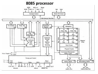
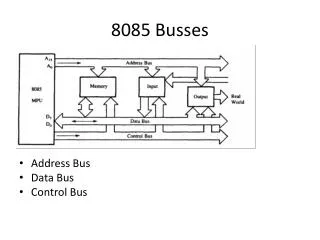
Accumulator Register Array ALU Memory Pointer Registers Flags Instruction Decoder Timing and Control Unit 2. Programming model of 8085 16-bit Address Bus 8-bit Data Bus Control Bus
8- Lines Bidirectional 16- Lines Unidirectional
Overview: 8085 Programming model • Six general-purpose Registers • Accumulator Register • Flag Register • Program Counter Register • Stack Pointer Register
Six general-purpose registers • B, C, D, E, H, L • Can be combined as register pairs to perform 16-bit operations (BC, DE, HL) • Accumulator – identified by name A • This register is a part of ALU • 8-bit data storage • Performs arithmetic and logical operations • Result of an operation is stored in accumulator
Flag Register • This is also a part of ALU • 8085 has five flags named • Zero flag (Z) • Carry flag (CY) • Sign flag (S) • Parity flag (P) • Auxiliary Carry flag (AC)
These flags are five flip-flops in flag register • Execution of an arithmetic/logic operation can set or reset these flags • Condition of flags (set or reset) can be tested through software instructions • 8085 uses these flags in decision-making process
Program Counter (PC) • A 16-bit memory pointer register • Used to sequence execution of program instructions • Stores address of a memory location • where next instruction byte is to be fetched by the 8085 • when 8085 gets busy to fetch current instruction from memory • PC is incremented by one • PC is now pointing to the address of next instruction
Stack Pointer Register • a 16-bit memory pointer register • Points to a location in Stack memory • Beginning of the stack is defined by loading a 16-bit address in stack pointer register
3.Instruction Set of 8085 • Consists of • 74 operation codes, e.g. MOV • 246 Instructions, e.g. MOVA,B • 8085 instructions can be classified as • Data Transfer (Copy) • Arithmetic • Logical and Bit manipulation • Branch • Machine Control
1. Data Transfer (Copy) Operations • Load a 8-bit number in a Register • Copy from Register to Register • Copy between Register and Memory • Copy between Input/Output Port and Accumulator • Load a 16-bit number in a Register pair • Copy between Register pair and Stack memory
Load a 8-bit number 4F in register B Copy from Register B to Register A Load a 16-bit number 2050 in Register pair HL Copy from Register B to Memory Address 2050 Copy between Input/Output Port and Accumulator MVIB, 4FH MOVA,B LXIH, 2050H MOVM,B OUT 01H IN 07H Example Data Transfer (Copy) Operations / Instructions
2. Arithmetic Operations • Addition of two 8-bit numbers • Subtraction of two 8-bit numbers • Increment/ Decrement a 8-bit number
Add a 8-bit number 32H to Accumulator Add contents of Register B to Accumulator Subtract a 8-bit number 32H from Accumulator Subtract contents of Register C from Accumulator Increment the contents of Register D by 1 Decrement the contents of Register E by 1 ADI 32H ADDB SUI 32H SUB C INR D DCR E Example Arithmetic Operations / Instructions
3. Logical & Bit Manipulation Operations • AND two 8-bit numbers • OR two 8-bit numbers • Exclusive-OR two 8-bit numbers • Compare two 8-bit numbers • Complement • Rotate Left/Right Accumulator bits
Logically AND Register H with Accumulator Logically OR Register L with Accumulator Logically XOR Register B with Accumulator Compare contents of Register C with Accumulator ComplementAccumulator RotateAccumulator Left ANAH ORAL XRA B CMP C CMA RAL Example Logical & Bit Manipulation Operations / Instructions
4. Branching Operations These operations are used to control the flow of program execution • Jumps • Conditional jumps • Unconditional jumps • Call & Return • Conditional Call & Return • Unconditional Call & Return
Jump to a 16-bit Address 2080H if Carry flag is SET Unconditional Jump Call a subroutine with its 16-bit Address Return back from the Call Call a subroutine with its 16-bit Address if Carry flag is RESET Return if Zero flag is SET JC 2080H JMP 2050H CALL 3050H RET CNC 3050H RZ Example Branching Operations / Instructions
5. Machine Control Instructions These instructions affect the operation of the processor. For e.g. HLT Stop program execution NOP Do not perform any operation
4. Writing a Assembly Language Program • Steps to write a program • Analyze the problem • Develop program Logic • Write an Algorithm • Make a Flowchart • Write program Instructions using Assembly language of 8085
Program 8085 in Assembly language to add two 8-bit numbers and store 8-bit result in register C. • Analyze the problem • Addition of two 8-bit numbers to be done • Program Logic • Add two numbers • Store result in register C • Example 10011001 (99H) A +00111001 (39H) D 11010010 (D2H) C
Get two numbers Add them Store result Stop Load 1st no. in register D Load 2nd no. in register E Translation to 8085 operations 3. Algorithm • Copy register D to A • Add register E to A • Copy A to register C • Stop processing
4. Make a Flowchart Start • Load 1st no. in register D • Load 2nd no. in register E Load Registers D, E Copy D to A • Copy register D to A • Add register E to A Add A and E • Copy A to register C Copy A to C • Stop processing Stop
Get two numbers Add them Store result Stop 5. Assembly Language Program • Load 1st no. in register D • Load 2nd no. in register E MVI D, 2H MVI E, 3H • Copy register D to A • Add register E to A MOV A, D ADD E • Copy A to register C MOV C, A • Stop processing HLT
Program 8085 in Assembly language to add two 8-bit numbers. Result can be more than 8-bits. • Analyze the problem • Result of addition of two 8-bit numbers can be 9-bit • Example 10011001 (99H) A +10011001 (99H) B 100110010 (132H) • The 9th bit in the result is called CARRY bit.
How 8085 does it? • Adds register A and B • Stores 8-bit result in A • SETS carry flag (CY) to indicate carry bit 10011001 99H A + 10011001 B 99H 0 1 10011001 00110010 99H 32H A CY
A CY • Storing result in Register memory 1 10011001 32H Register B Register C • Step-1 Copy A to C • Step-2 • Clear register B • Increment B by 1
2.Program Logic • Add two numbers • Copy 8-bit result in A to C • If CARRY is generated • Handle it • Result is in register pair BC
Load two numbers in registers D, E Add them Store 8 bit result in C Check CARRY flag If CARRY flag is SET Store CARRY in register B Stop Load registers D, E Translation to 8085 operations 3. Algorithm • Copy register D to A • Add register E to A • Copy A to register C • Copy A to register C • Use Conditional Jump instructions • Clear register B • Increment B • Stop processing
4. Make a Flowchart Start If CARRY NOT SET False Load Registers D, E Clear B Copy D to A Increment B True Add A and E Copy A to C Stop
5. Assembly Language Program • Load registers D, E MVI D, 2H MVI E, 3H • Copy register D to A • Add register E to A MOV A, D ADD E • Copy A to register C • Copy A to register C MOV C, A • Use Conditional Jump instructions JNC END MVI B, 0H INR B • Clear register B • Increment B • Stop processing HLT END:
4. Addressing Modes of 8085 • Format of a typical Assembly language instruction is given below- [Label:] Mnemonic [Operands] [;comments] HLT MVI A,20H MOVM,A ;Copy A to memory location whose address is stored in register pair HL LOAD:LDA2050H ;Load A with contents of memory location with address 2050H READ:IN07H ;Read data from Input port with address 07H
The various formats of specifying operands are called addressing modes • Addressing modes of 8085 • Register Addressing • Immediate Addressing • Memory Addressing • Input/Output Addressing
1. Register Addressing • Operands are one of the internal registers of 8085 • Examples- MOVA, B ADDC
2. Immediate Addressing • Value of the operand is given in the instruction itself • Example- MVIA, 20H LXIH, 2050H ADI 30H SUI 10H
3. Memory Addressing • One of the operands is a memory location • Depending on how address of memory location is specified, memory addressing is of two types • Direct addressing • Indirect addressing
3(a) Direct Addressing • 16-bit Address of the memory location is specified in the instruction directly • Examples- LDA2050H ;load A with contents of memory location with address 2050H STA3050H ;store A with contents of memory location with address 3050H
3(b) Indirect Addressing • A memory pointer register is used to store the address of the memory location • Example- MOVM, A;copy register A to memory location whose address is stored in register pair HL H L A 30H 20H 50H 30H 2050H
4. Input/Output Addressing • 8-bit address of the port is directly specified in the instruction • Examples- IN 07H OUT 21H
5. Instruction & Data Formats 8085 Instruction set can be classified according to size (in bytes) as • 1-byte Instructions • 2-byte Instructions • 3-byte Instructions
1. One-byte Instructions • Includes Opcode and Operand in the same byte • Examples-