Download

1 / 16
210 likes | 512 Views
8085 Interrupts. Interrupts. When a microprocessor is interrupted, it stops executing its current program and calls a special routine which “services” the interrupt The event that causes the interruption is called Interrupt

E N D
Interrupts • When a microprocessor is interrupted, it stops executing its current program and calls a special routine which “services” the interrupt • The event that causes the interruption is called Interrupt • The special routine executed to service the interrupt is called ISR - Interrupt Service Routine/Procedure
Interrupt classification • Hardware InterruptAn interrupt caused by an “External signal ” • Software Interrupt An interrupt caused by “Special Instruction” • Maskable InterruptsCan be delayed or Rejected • Non-Maskable Interrupts Can not be delayed or Rejected (Service must) • VectoredWhere the subroutine starts is referred to as Vector Location • Non-vectored The address of the service routine needs to be supplied externally by the device
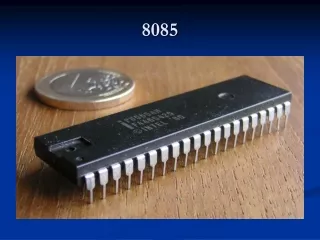
8085 Interrupts TRAP RST7.5 RST6.5 RST 5.5 INTR INTA 8085 The ‘EI’ instruction is a one byte instruction and is used to Enable the non-maskable interrupts. The ‘DI’ instruction is a one byte instruction and is used to Disable the non-maskable interrupts.
Interrupt Vectors & the Vector Table • An interrupt vector is a pointer to where the ISR is stored in memory. • All interrupts (vectored or otherwise) are mapped onto a memory area called the Interrupt Vector Table (IVT). • The IVT is usually located in (0000H - 00FFH). Vector Address = Interrupt number * 8
Software Interrupt • The 8085 recognizes 8 RESTART instructions: RST n ( RST0 - RST7) • Each of these would send the execution to a redetermined hard-wired memory location:
The 8085 Maskable/Vectored Interrupt Process • The interrupt process should be enabled using the EI instruction. • The 8085 checks for an interrupt during the execution of every instruction. • If there is an interrupt, and if the interrupt is enabled using the interrupt mask, the microprocessor will complete the executing instruction, and reset the interrupt flip flop. • The microprocessor then executes a call instruction that sends the execution to the appropriate location in the interrupt vector table.
The 8085 Maskable/Vectored Interrupt Process • When the microprocessor executes the call instruction, it saves the address of the next instruction on the stack. • The microprocessor jumps to the specific service routine. • The service routine must include the instruction EI to re-enable the interrupt process. • At the end of the service routine, the RET instruction returns the execution to where the program was interrupted.
7 6 5 4 3 2 1 0 M5.5 M7.5 M6.5 MSE SDO R7.5 SDE XXX SIM value must be loaded in Accumulator SIM – Serial interrupt mask } RST5.5 Mask 0 - Available 1 - Masked Serial Data Out Either 0 or 1 RST6.5 Mask RST7.5 Mask Mask Set Enable 0 - Ignore bits 0-2 1 - Set the masks according to bits 0-2 Enable Serial Data 0 - Disable 1 - Enable Force RST7.5 Flip Flop to reset Not Used
Example MSE Mask Set Enable RST 6.5 Mask RST 5.5 & 7.2 Unmask RST FF Don’t Reset Serial Data Igonered M7.5 M6.5 M5.5 SDO MSE R7.5 SDE XXX 1 0 0 0 0 0 1 0 Contents of accumulator are: 0AH EI ; Enable interrupts including INTR MVI A, 0A ; Prepare the mask to enable RST 7.5, and 5.5, disable 6.5 SIM ; Apply the settings RST masks
Example MSE Mask Set Disable RST FF Reset Serial Data Enable Serial Data output is 0 M7.5 M6.5 M5.5 SDO MSE R7.5 SDE XXX 0 1 0 1 0 1 0 0 Contents of accumulator are: 54H
7 6 5 4 3 2 1 0 M5.5 M7.5 M6.5 IE SDI P6.5 P7.5 P5.5 Rim – read interrupt mask } RST5.5 Mask 0 - Available 1 - Masked Serial Data In RST6.5 Mask RST7.5 Mask RST5.5 Interrupt Pending RST6.5 Interrupt Pending Interrupt Enable Value of the Interrupt Enable Flip Flop RST7.5 Interrupt Pending Set – 1 Reset - 0 Copies the status of the interrupts into the accumulator
Example Interrupt Enable RST 5.5 & 6.5 Masked RST 7.5 Pending Serial Input Data is 0 M7.5 M6.5 M5.5 SID IE P5.5 P7.5 P6.5 1 0 0 1 0 0 1 1 Contents of accumulator are: 4BH