Download
1 / 36
360 likes | 364 Views
The CMS Tracker Silicon sensor and electronic system. A brief introduction to a part of CMS where Imperial played a major role A practical example Some material intended to complement the silicon sensor & electronics lectures with the practical implications of building such detectors. HCAL.

E N D
The CMS TrackerSilicon sensor and electronic system A brief introduction to a part of CMS where Imperial played a major role A practical example Some material intended to complement the silicon sensor & electronics lectures with the practical implications of building such detectors
HCAL Muon chambers Tracker ECAL 4T solenoid CMS Compact Muon Solenoid Total weight: 12,500 t Overall diameter: 15 m Overall length 21.6 m Magnetic field 4 T PGs
The Compact Muon Solenoid experiment • a general purpose detector for studying the full range of physics at the CERN Large Hadron Collider • expected to operate (nominally) for 10 years • ~500fb-1 with high radiation levels in tracking volume • operation with heavy ions: ~ 1 month annually • The All-Silicon Tracker • R ≈ 4 – 11 cm pixels • R ≈ 25 – 115 cm silicon microstrip detectors designed for general purpose tracking of charged particles in CMS PGs
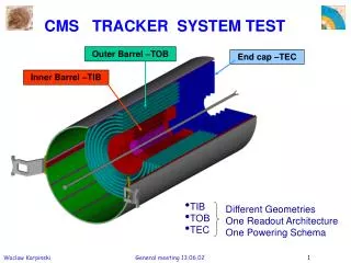
TOB TOB TEC TEC TIB TIB TID TID PD PD CMS Tracker and its sub-systems • Two main sub-systems: Silicon Strip Tracker and Pixels • pixels quickly removable for beam-pipe bake-out or replacement • SST not replaceable in reasonable time PGs
Tracker Electronic System • Main features • Analogue readout • No on-detector zero suppression • Optical analogue data transfer • Control signals sent optically • Local electrical transfer • Custom electronics on detector • radiation hard ASICs and optoelectronics • Off-detector electronics • underground outside radiation zone • ADCs and zero suppression • ~500 FEDs, including spares • ~25 FECs DAQ PGs
pipeline 128x192 APSP + 128:1 MUX 128 x preamp/shaper 7.1mm control logic bias gen. FIFO pipe logic CAL 8.1 mm APV25 • Main features (many innovative, at the time) • Commercial 0.25µm CMOS ASIC • 128 readout channels • 50 ns CR-RC amplifier • 192 cell pipeline memory • alternate operating modes • peak & deconvolution • on-chip analogue signal processing • various ancillary functions • eg calibration, I2C, programmable latency… APV O/P Frame Peak Decon. digital header 128 analogue samples PGs
Optical links • System developed for CMS Tracker mainly by CERN with industrial partners • vital technology, established for particle physics during LHC construction • “noise free”, low power, high speed data transmission • 1.3µm single mode FP laser transmitters, III-V semiconductor Tx & Rx • good linearity over wide range, good radiation & B-field tolerance PGs
Now seems modest in comparison with latest technology Front End Driver JTAG Programmable digital logic board • opto-electric conversion • digitisation • data reordering • baseline subtraction • hit finding • zero suppression • data transfer via high speed S-link • VME control and slow readout OptoRx VME64x 9U board CFlash 34 x FPGAs 96 channels Memories Analogue Power TTC FE Unit “Primary” Side PGs
Tracking in CMS: strategy • No detector of this type existed and LHC at 1034 cm-2s-1 is a very special challenge • ~35 events per crossing @ 40MHz: many 100s of tracks/event (radiation damage) • pileup of (partial) signals from previous beam crossings • Rely on “few” measurement layers • each able to provide robust (clean) and precise coordinate • 2-3 pixel and 10-14 µstrip measurements • low material is an important objective 150 x 100 µm2 pixels s ~ 10µm • Originally much uncertainty about performance vs number of layers • software for track reconstruction built at same time as simulations and detector • Pixels provide precise 3D points in most congested region for seeding tracks in outer layers 22 cm 93 cm PGs
Measured points Total number of hits: Double-side hits Double-side hits in thin detectors Double-side hits in thick detectors 6 TOB layers 4 TIB layers 9 TEC disks 3 TID disks PGs
Performance from simulation Transverse impact parameter Transverse momentum resolution multiple scattering dominated depends on pixel space point precision Both IP and momentum measurement depend on curvature measurement So performance limited by Npoints, point precision, lever arm (& B) and multiple scattering What is actually required? s(p) -> s(m): measure Z peak with natural width spatial: to have good efficiency for b-decays PGs
Effect of material on particles in the Tracker • Nuclear interactions destroy and create particles Vast majority of particles have low momentum PGs
Effect of material on measurements • compare real life with idealised detector: material reduced by factor 100 • Simplified – but adequate – calculation PGs
Summary of requirements for tracking detector • Minimum material - but moderate number of layers • limit atomic (multiple scattering) and nuclear interactions • Low power (to minimise material but cooling is not easy) • in practice 3.6 mW/channel for SST (~10M) and 55 µW/pixel (~66M) • Low electronic noise • max 2000 e (~250 e pixels) but sufficiently low thresholds for low occupancy • occupancy 1-2% strips, 0.05% pixels, but tolerant to large fluctuations (eg HI) • Operation in 4T B-field and T ≈ -20°C • Ionising Dose & Single Event Effect radiation tolerant • Robust, stable, reliable for long time with little or no access • simple (!) to operate, set up, control, calibrate and align • result of overall engineering, electronic design, and analogue information • very large software & significant firmware effort over long period • Once all the above achieved, with sufficient granularity (& correct sensors etc) should guarantee good spatial precision! PGs
Snapshots of Constructionby worldwide effortAustria, Belgium, Finland, France, Germany, Italy, CERN, Switzerland, UK, USA – currently 62 institutesmuch movement of components and assembliesSensors, ASICs, hybrids procured and tested some parts commercially: e.g. hybridsModules constructed in our dedicated centres, using automated assembly methods… PGs
Module components Pins Front-End Hybrid APV and control chips Kapton cable Now incorporated with the hybrid. Pitch Adapter Kapton Bias Circuit Carbon Fiber/Graphite Frame Silicon Sensors PGs
Modules and sub-system assembly Inner barrel shells (Italy) TOB modules and Rods (US, CERN) Hybrids (industry) Endcap petals (Au, Ge, Be, Fr) PGs
Integration at TIF • Dedicated Tracker Integration Facility in CERN lab • assembled sub-systems, then added external cables, cooling, … PGs
Pixel assembly PGs
Complex, congested routes Tracker services • Installation of services was one of the most difficult jobs to complete CMS It may be impossible to replace cables and cooling for upgrades PFE ≈ 33kW I=15,500A PS = 300kVA PGs
RESULTS PGs
Material budget • Final Significantly larger than hoped for in early design TDR Distorted plot to match scales PGs
Signal to noise • Measured in deconvolution mode • 25 ns peaking time • Characteristic “Landau” shape results from statistical sampling of electromagnetic scatters (Coulomb) in thin layer • occasional large fluctuations APV25 response Adequate linearity to measure most of signal range output signal [MIPs] input signal injected [MIPs] PGs
Tracking performance Very early results – many more published • Major software task • but strongly correlated to basic performance • alignment & calibration • mechanical and thermal stability • signals well separated from noise • point measurement precision • Several track finding algorithms in use (GeV/c) Considerable advance on original tracking objectives from TDR era partially compensates for material in system PGs
Material distribution • Radiographs using particles • reconstruct nuclear interactions • similar plots also obtained using photon conversions • detailed understanding essential for physics backgrounds PGs
Secondary – long-lived- decays Ks -> p+p- L0 -> pp- The relevance: indicates quality of tracking & understanding of backgrounds, modelling of material (excellent agreement with Monte Carlos from early stage) checks on magnetic field (most of K0 mass appears as momentum) PGs
Baryon resonances Excited, short lived states. The W- [sss] was the prediction [Gell-Mann 1962] which began to make most people believe in quarks. Ξ- Ω- PGs
X-Lp- pp-p- Two detached vertices X- cascade reconstruction L pp- X-Lp- PGs
Energy loss Means of limited particle identification • For dE/dx, need to know conversion ratio electrons/ADC count • Use cosmic muons (MIP) to calibrate all APVs → uniformity • Path length corrected MPV of Signal systematicuncertainties • Most probable energy loss/unit length • Use Landau-Vavilov-Bichsel theory • Fit as function of track momentum • Extract calibration constant for each sensor type PGs
dE/dx in collisions deuterons • Clear separation of kaons and protons, nice agreement with MC • Cut dE/dx > 4.15 MeV/cm PGs
Pixels PGs
Lorentz angle in pixels This is the trick which gives ~10µm resolution from 100µm pixels • ExB fields • enhances charge sharing between pixels • analogue interpolation improves precision B field for barrel/endcap Barrel Endcap PGs
Summary • The huge tracking system is perhaps the most remarkable CMS detector • a lot of advanced technology was mastered • System has been very reliable and robust, with no significant problems • some radiation effects beginning to be visible (as expected) • Software and analysis working exceptionally well • The tracker contributes to almost all physics from CMS • primary and secondary particle reconstruction • particle flow • µ momentum • calorimeter shower identification and background removal • The replacement in ~2023 will be even harder • and more demanding performance too PGs