Download
1 / 14
140 likes | 277 Views
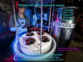
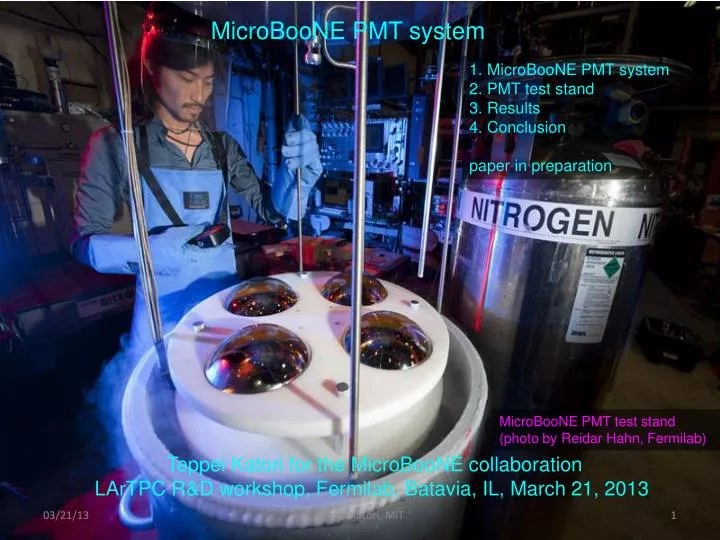
MicroBooNE PMT system. 1. MicroBooNE PMT system 2. PMT test stand 3. Results 4. Conclusion paper in preparation. MicroBooNE PMT test stand (photo by Reidar Hahn, Fermilab). Teppei Katori for the MicroBooNE collaboration LArTPC R&D workshop, Fermilab, Batavia, IL, March 21, 2013.

E N D
MicroBooNE PMT system 1. MicroBooNE PMT system 2. PMT test stand 3. Results 4. Conclusion paper in preparation MicroBooNE PMT test stand (photo by Reidar Hahn, Fermilab) Teppei Katori for the MicroBooNE collaboration LArTPC R&D workshop, Fermilab, Batavia, IL, March 21, 2013 Teppei Katori, MIT
1. MicroBooNE photo detection system 30 of 8-inch PMTs - R5912-02mod, 14 stage, bi-alkali + Pt coating PMT - Custom design cryogenic base (positive HV operation) - TPB coated acrylic plate in front of PMT - Cryogenic magnetic shield All PMTs are tested at PMT test stand (today’s talk) MicroBooNE Cryostat with TPC PMT mount mock up system at Fermilab Lab F Teppei Katori, MIT
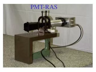
2. PMT test stand Purpose - All PMTs need to be operated in cryogenic temperature before the experiment - Verify spec gain and dark current in cryogenic condition - Gain experiences of cryogenic PMT operation - Study basic features (how long do you need to cool down, etc) No need to be pressurized vessel (expensive, safety issue) Large open Dewar with modification - commercial open Dewar, 346L (70cmx90cm inner diameter and height), $17,000 - Labor + Materials ~ $5000 - Total $22,000 - Need 1 or 2 of 160L LN2 bottle to fill every week (LN2~$30, LAr~$160) - No need technician’s help for operation Test procedure - 4 PMTs are simultaneously immersed in LN2 - 1 PMT (calibration PMT) stays same location during all tests - PMTs are immersed in LN2 least 3 days with dark before any tests - LED illumination + trigger in LN2 (no purity issue) Teppei Katori, MIT
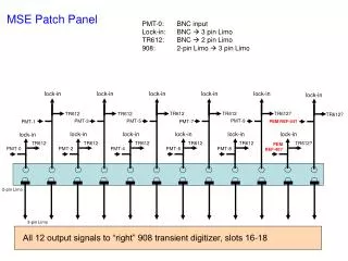
2. PMT test stand Lid - All structures are attached on glass fiber lid - there are 5 penetrations i. LN2 injection ii. gas vent iii. level sensor iv. cable feed-through v. light injection system Teppei Katori, MIT
2. PMT test stand Lid - All structures are attached on glass fiber lid - there are 5 penetrations i. LN2 injection ii. gas vent iii. level sensor iv. cable feed-through v. light injection system Fiber is coupled to LED outside of Dewar, sand blasted diffuser illuminate all PMTs Teppei Katori, MIT
2. PMT test stand Lid - All structures are attached on glass fiber lid - there are 5 penetrations i. LN2 injection ii. gas vent iii. level sensor iv. cable feed-through v. light injection system PMT fixture - In room temperature, PMTs sit on Delrin bottom fixture - In LN2, PMTs float and fit in Delrin upper fixture - There is a weight at the bottom of the structure Teppei Katori, MIT
3. PMT Test results Long term stability PMTs are prepared in the test stand ~3days. Then PMT HVs are suddenly turned on. Measured PEs are stable, so the system is stable. PMT gains are stabilized within 1hr, there is no drift. There is no special care to turn on/off HVs in LN2. Teppei Katori, MIT
3. PMT Test results Cooling test PMTs are suddenly immersed in LN2. Then PMT HVs are turned on. Measured PEs are not stable (failure to prepare PMT in dark) PMT gains change dramatically. PMTs should be kept long enough before any test (3 days). Teppei Katori, MIT
Typical SER plot 3. PMT Test results PMT gain PMT gain is extrapolated from SER plot. Gains are measured at every 100V from 900V to 1800V. PMT cold gains are ~10-50% of warm gains. Optimal HV value for 3E7 gain is extrapolated. Typical warm and cold gain Teppei Katori, MIT
Typical SER plot Typical SER plot 3. PMT Test results PMT gain PMT gain is extrapolated from SER plot. Gains are measured at every 100V from 900V to 1800V. PMT cold gains are ~10-50% of warm gains. Optimal HV value for 3E7 gain is extrapolated. ~200V increase can recover gain drop. Optimal HV distribution for 3E7 gain Teppei Katori, MIT
3. PMT Test results PMT dark current PMT dark current (count/sec with fixed threshold) is measured Cold dark current is slightly higher than warm dark current. Cold noise doesn’t show “plateau break down” at higher HV. These results are not intuitive, but in fact, well known. NIMA621(2010)437 JINST2(2007)P11004 ArXiv:0805.0771 Typical dark current curve Teppei Katori, MIT
3. PMT Test results PMT gain LED rate dependence? PMTs are prepared in the test stand ~3days. Then PMT HVs are suddenly turned on with higher LED frequency (10kHz, instead of 10Hz). PMT gains take ~1day to be stabilized. Gain plateau is lower than 10Hz LED measurement. Gain is sensitive with any changes (LED rate, PMT HVs), and show hysteresis. Typical dark current curve Teppei Katori, MIT
3. PMT Test results PMT gain LED rate dependence? PMTs are prepared in the test stand ~3days. Then PMT HVs are suddenly turned on with higher LED frequency (10kHz, instead of 10Hz). Implication - Surface running LAr detectors (e.g., MicroBooNE) receive ~10kHz cosmic ray. Cryogenic PMT operation may need special care for surface running. Teppei Katori, MIT
4. Conclusion All PMTs are tested both in air, and LN2. There is no PMT obviously broken. A calibration PMT is cryo-cycled ~10 times, but no visible damage. Although QE is not monitored, same LED intensity and same HV provide same pulse height etc. Status of MicroBooNE photo-detection system - PMTs are ready - PMT mounts will be fabricated - PMT signal + HV feed-through will be ordered soon - whole system is ready to be installed in the cryostat this early summer Thank you for your attention Teppei Katori, MIT