Download
1 / 21
210 likes | 365 Views
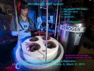
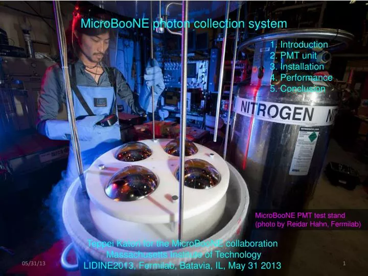
MicroBooNE photon collection system. 1. Introduction 2. PMT unit 3. I nstallation 4. Performance 5. Conclusion. MicroBooNE PMT test stand (photo by Reidar Hahn, Fermilab). Teppei Katori for the MicroBooNE collaboration Massachusetts Institute of Technology

E N D
MicroBooNE photon collection system 1. Introduction 2. PMTunit 3. Installation 4. Performance 5. Conclusion MicroBooNE PMT test stand (photo by Reidar Hahn, Fermilab) Teppei Katori for the MicroBooNE collaboration Massachusetts Institute of Technology LIDINE2013, Fermilab, Batavia, IL, May 31 2013
1. Introduction 2. MicroBooNE PMT unit 3. Installation 4. Performance 5. Conclusion Teppei Katori, MIT
1. Introduction MicroBooNE is 170 ton liquid argon cryostat with 2.5m x 2.4m x 10.6m volume of TPC (under construction, beam data is expected from 2014) tour yesterday Prompt scintillation light from argon is faster (~ns) than electron drift (~ms), therefore detection of scintillation light allows to trigger the TPC Large array of large photo-cathode PMT is the cheapest option to achieve this purpose We took basic features of ICARUS T600 PMT system design and modified MicroBooNE cryostat MicroBooNE TPC Teppei Katori, MIT
ICARUS collaboration, Technical Memo/06-03 (unpublished) 1. Introduction ICARUS T600 photon detection system - ETL 12 stage 8-inch bi-alkali PMT with Pt-coating - 54 of PMTs to cover T300 3.6m x 3.9m x 19.6m volume (~0.5% photo-cathode coverage) - PMTs are located 5mm behind of collection wire plane - PMT windows are sand blasted to spray TPB solution - Negative HV operation, custom made base directly soldered on PMT - PEEK rod PMT mount Inside of half module of ICARUS T300 wire planes cathode PMT Teppei Katori, MIT
ICARUS collaboration, Technical Memo/06-03 (unpublished) 1. Introduction ICARUS T600 photon detection system vs MicroBooNE photon detection system - ETL 12 stage 8-inch bi-alkali PMT with Pt-coating Hamamatsu 8-inch tube - 54 of PMTs to cover T300 3.6m x 3.9m x 19.6m volume (~0.5% photo-cathode coverage) 0.85% photocathode coverage - PMTs are located 5mm behind of collection wire plane ~20cm behind of collection wire plane - PMT windows are sand blasted to spray TPB solution TPB plate equipped in front of PMT - Negative HV operation, custom made base directly soldered on PMT positive HV operation - PEEK rod PMT mount spring loaded wire mount ICARUS T600 MicroBooNE Teppei Katori, MIT
1. Introduction 2. MicroBooNE PMT unit 3. Installation 4. Performance 5. Conclusion Teppei Katori, MIT
Briese et al, ArXiv:1304.0821 2. MicroBooNE PMT unit PMT unit mechanical model Each PMT unit consists of 4 pieces - PMT and base - TPB plate - PMT mount - Cryogenic mu-metal shield Teppei Katori, MIT
Briese et al, ArXiv:1304.0821 - PMT and base - TPB plate - PMT mount - Cryogenic mu-metal shield 2. PMT and base Hamamatsu R5912-02mod - 14 stage high gain, 8-inch hemi-spherical photocathode, Pt-coating - 32 PMTs to cover 2.5m x 2.4m x 10.6m volume (0.85% photocathode coverage) - All PMTs are tested at PMT test stand (next) Cryogenic base - Metal film resistor, NP0/C0G capacitor, glass reinforced PC board, Teflon cable, etc - Layout is designed at Fermilab - Positive HV operation One cable carries both signal and HV - Total heat ~ 0.5W MicroBooNE PMT base Teppei Katori, MIT
Briese et al, ArXiv:1304.0821 - PMT and base - TPB plate - PMT mount - Cryogenic mu-metal shield 2. PMT test stand MicroBooNE PMT test stand Open Dewar based PMT test stand - Dark current and gain are measured both in air and liquid nitrogen (LN2). - Operation HV values in cryogenic temperature are extracted. Distribution of optimal HV values (gain=3E7) room temperature liquid nitrogen Teppei Katori, MIT
Baptista et al, ArXiv:1210.3793 - PMT and base - TPB plate - PMT mount - Cryogenic mu-metal shield 2. TPB plate TPB coated acrylic plate in front of PMT - TPB + polystyrene solution is deposited on acrylic plate - Cheaper and easier option than sand blast, vacuum evaporation, etc - Our study shows geometric loss is small if the plate is close (<1cm) and big (>10 inch) TPB plate production - 50% TPB + 50% polystyrene by mass in Toluene solution is applied on acrylic plate by brush - Easily produce ~30 plates within 1 week 12 inch acrylic plate in front of the PMT will give order 1% global collection efficiency. >10 inch <1cm Teppei Katori, MIT
- PMT and base - TPB plate - PMT mount - Cryogenic mu-metal shield 2. Mounting structure Spring loaded wire - PMT is held in Teflon-aluminum structure by Teflon coated wire under tension by springs - Thermal expansion/contraction is taken into account - being produced at Fermilab machine shop PMT unit mechanical model Teflon coated wire spring Teppei Katori, MIT
Calvo et al, NIMA621(2010)222 - PMT and base - TPB plate - PMT mount - Cryogenic mu-metal shield 2. Cryogenic magnetic field shield Cryogenic magnetic shield - Double Chooz study shows earth magnetic field (~0.5G) reduces ~40% light output - MicroBooNE cryostat is made of non-magnetic stainless steel (SL304) Double Chooz PMT B-filed response -500 Teppei Katori, MIT
paper in preparation - PMT and base - TPB plate - PMT mount - Cryogenic mu-metal shield 2. Cryogenic magnetic field shield PMT B-field test stand - We built a test stand to check the effect of earth magnetic field - Cryogenic magnetic field shield prevent light yield variation due to PMT angle - We apply the shield up to the equator permeability with function of temperature m4 100,000 50,000 0 cryogenic mu-metal mu-metal equator MicriBooNE PMT rotator -200 -100 0 +20 (Co) optical fiber cryogenic mu-metal shield Teppei Katori, MIT
paper in preparation - PMT and base - TPB plate - PMT mount - Cryogenic mu-metal shield 2. Cryogenic magnetic field shield PMT B-field test stand - We built a test stand to check the effect of earth magnetic field - Cryogenic magnetic field shield prevent light yield variation due to PMT angle - We apply the shield up to the equator equator Relative signal variation with PMT angle Relative signal variation Full shield No shield Equator shield Paul Nienaber (St. Mary) Ryan Grosso (Cincinnati) Bryce Littlejohn (Cincinnati)
1. Introduction 2. MicroBooNE PMT unit 3. Installation 4. Performance 5. Conclusion Teppei Katori, MIT
See Christina Ignarra’s talk (May 31afternoon) 3. PMT rack TPC frame – PMT rack installation practice PMT rack - 32 PMT units + 4 light guides are mounted on PMT rack (light guides installation is under TB discussion) - They are configured to see inside of TPC between TPC frame bars PMT rack TPC frame PMT rack layout Teppei Katori, MIT
3. Installation In ICARUS, PMTs need to be installed first, and sit months there is a worry of degradation of TPB coating... Oil-free linear (Thomson) bearing - Racks slide in and out by Teflon coated Thomson bearing - PMTs can be installed after TPC is installed See Jenn VenGemert’s talk (May 30 afternoon) PMT rack bottom linear bearing structure PMT installation practice Teppei Katori, MIT
3. Installation In ICARUS, PMTs need to be installed first, and sit months there is a worry of degradation of TPB coating... Oil-free linear (Thomson) bearing - Racks slide in and out by Teflon coated Thomson bearing - PMTs can be installed after TPC is installed wire planes cathode Inside of half module of ICARUS T300 MicroBooNE PMT mock set up TPC frame wire planes PMT PMT MicroBooNE photon detection system will be installed in the cryostat in summer 2013 Teppei Katori, MIT
1. Introduction 2. MicroBooNE PMT unit 3. Installation 4. Performance 5. Conclusion Teppei Katori, MIT
4. Performance MicroBooNE simulation (cosmic ray overlaid) Flash Finder - Time and coordinate cluster of PMT pulses can find neutrino related activity in the sea of cosmic rays (~20 cosmic rays per TPC window) cluster of PMT pulses ”flash” Time PMT ID Teppei Katori, MIT Ben Jones (MIT)
Conclusion MicroBooNE photon detection system consists of 32 cryogenic PMTs and 4 lightguides PMT unit consists of 4 pieces; PMT and base, TPB plate, PMT mount, and cryogenic mu-metal shield System is well-understood, and ready to install in the MicroBooNE cryostat in this summer MicroBooNE collaboration Thank you for your attention! Teppei Katori, MIT